
Dynamic bit rate control process

a bit rate control and bit rate control technology, applied in the field of dynamic bit rate control process, can solve the problems of signal data onto quantized values that produces some loss in accuracy, and generates signal distortion

Inactive Publication Date: 2003-05-01
SONIC IP
View PDF1 Cites 28 Cited by
  • Summary
  • Abstract
  • Description
  • Claims
  • Application Information

AI Technical Summary

Benefits of technology

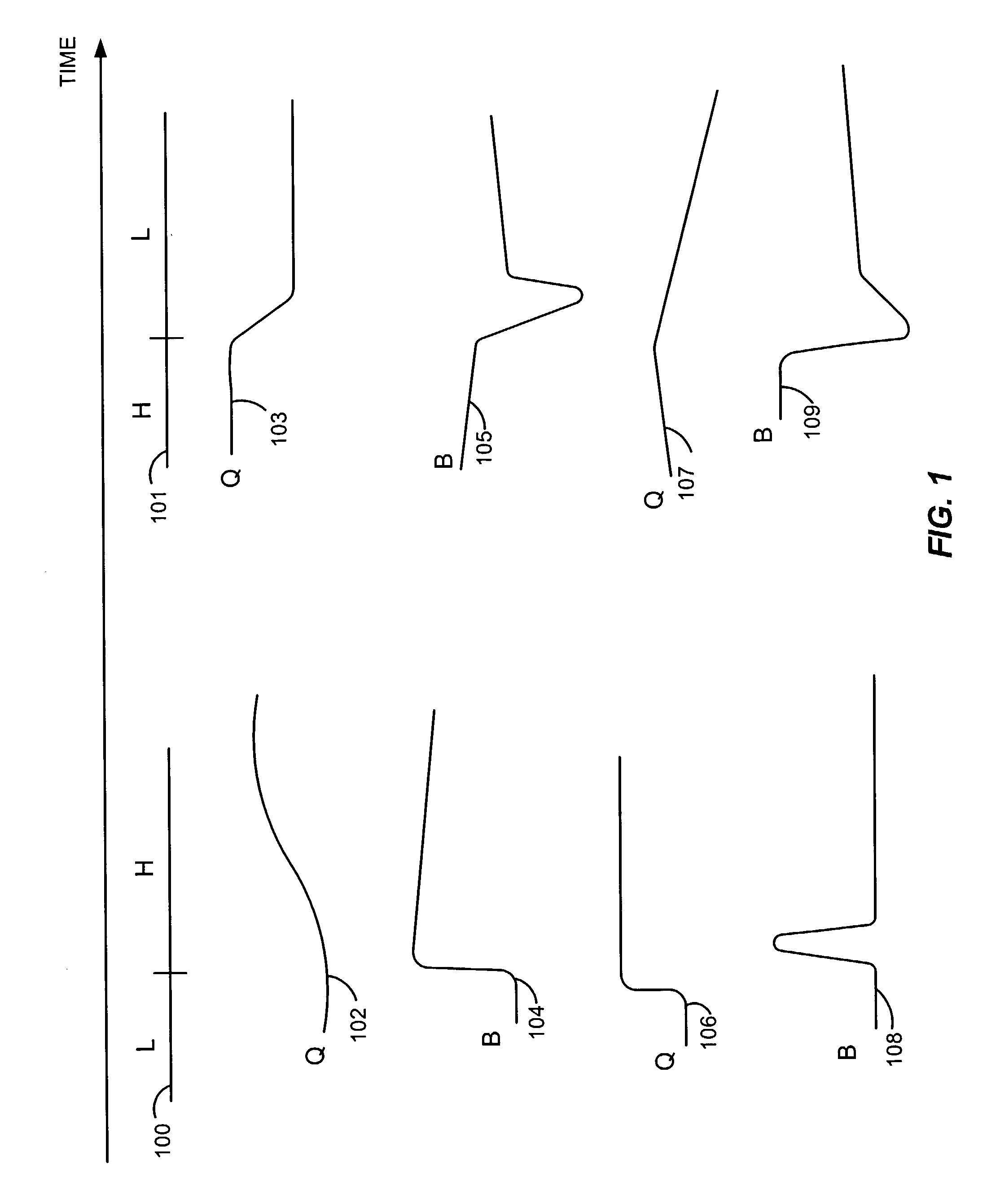
[0015] Furthermore, the present invention provides a method of bit rate control wherein two different averaging periods are employed to meet a long term bit rate target and to achieve a short term quick reaction. In addition, the present invention provides a system of bit rate control, which includes using an adjustable coding quantizer or other bit rate controller that proportionate the current achieved bit rate with the target bit rate. According to an embodiment of the present invention, the bit rate control is relaxed during high motion scenes to allow high peaks of bit rate at those points. The coding means reacts slowly to transitions from low to high motion sequences to preserve the best overall video quality.
[0016] The present invention further provides a method of performing rate control that is capable of achieving a preset overall bit rate and further providing the ability to optimize the distribution among frames for best overall quality. The method can perform dynamic forecasting of average compensation using asymmetrical reaction to high speed and low speed motions. The average can be a simple average, a weighted average, e.g., an exponential moving average, or any other moving average methods. Two moving averages are used to record the average bit rates, both in a long averaging period for providing overall rate control and in a short reaction period for providing reaction to immediate change in scenes.
[0017] The long averaging period average determines the target bit rate for the current frame. The short reaction period average is then compared to the target bit rate. The quantizer and other coding parameters are adjusted accordingly in an asymmetrical manner. For example, the quantizer is turned up slowly if the reaction period average is above the long averaging period average, which usually signals a short term high motion burst. The quantizer is turned down quickly if the reverse is happening. The adjustment of the quantizer can be made proportional to the difference of the averages to avoid overreaction and oscillatory behaviors. Frame level quantizer can be determined before encoding the frame to enable better optimization of the encoding process.

Problems solved by technology

However, the available storage space and bandwidth for transmitting such signals is often limited.
Therefore, the encoding of the signal data onto the quantized values necessarily produces some loss in accuracy and generates some distortion of the signal after the decoding process.
A larger quantizer signals a coarse quantization step; hence a low data bit rate and poor video quality.
However, the mixture of high speed motion and low speed motion scenes and the transitions among them are drastically different from one video sequence to another.
On the other hand, a low bit rate often does not fully utilize the capacity of the transmission channel and recording media to achieve the maximum potential quality.
Thus, in the encoding of digital video data, a persistent problem has been how to accommodate any given movie sequence, and to allocate the available bits among the scenes to achieve the maximum overall quality.
Thus, in a method employing a fixed quantizer, there is no effective control over the bit rate.
Although this approach has been shown to work in low bit rate mobile application environment, it does not give satisfactory results for the high bit rate encoding of motion pictures.
Another challenge is that in dynamic coding, the coder only knows the past, i.e., the scenes that have already been encoded.

Method used


Image

  • Dynamic bit rate control process
  • Dynamic bit rate control process
  • Dynamic bit rate control process

Examples


Embodiment Construction

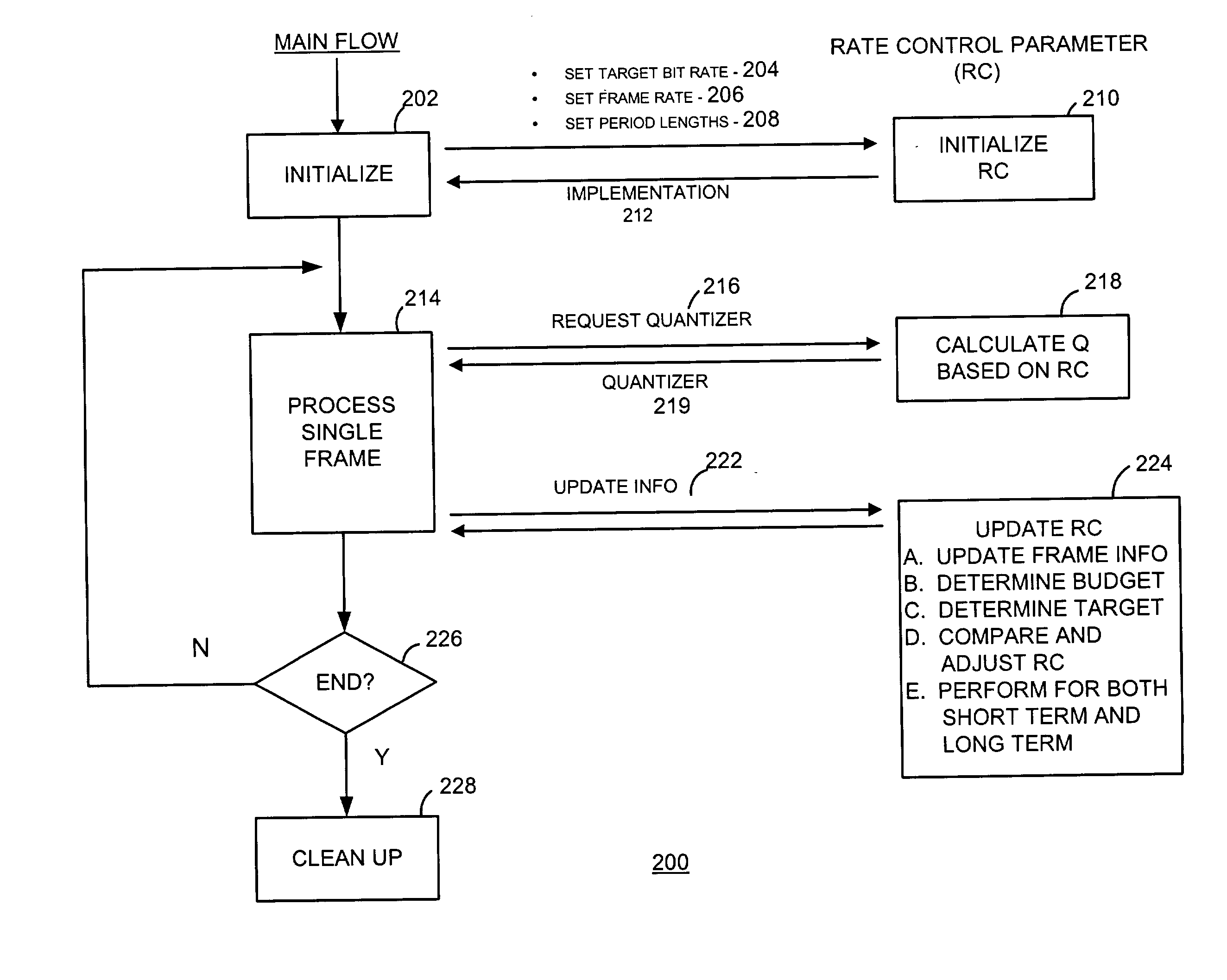
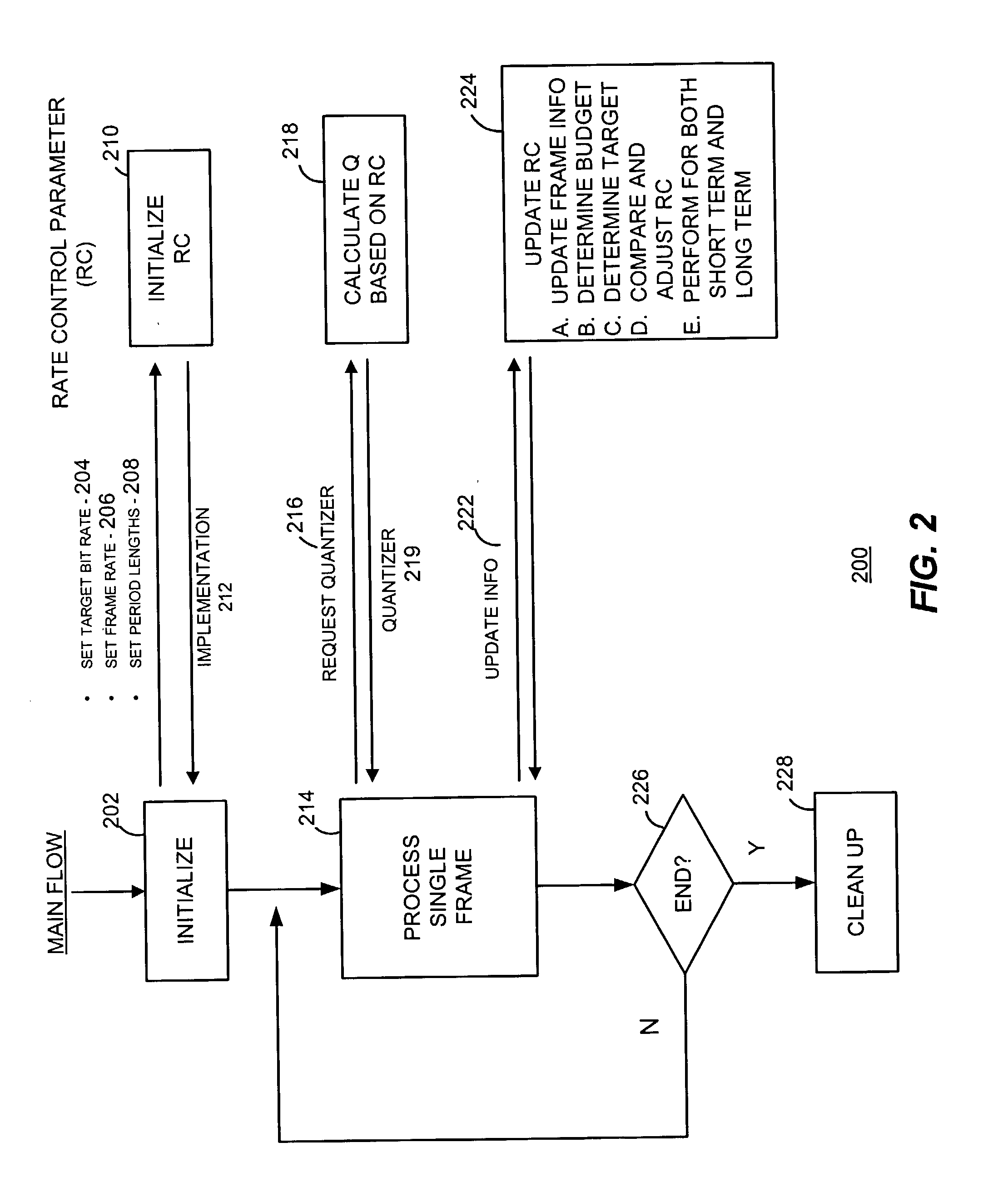
[0023] Various embodiments of the present invention are described hereinafter with reference to the figures. It should be noted that the figures are only intended to facilitate the description of specific embodiments of the invention. They are not intended as an exhaustive description of the invention or as a limitation on the scope of the invention. In addition, an aspect described in conjunction with a particular embodiment of the present invention is not necessarily limited to that embodiment and can be practiced in conjunction with any other embodiments of the invention.

[0024] FIG. 1 is a timing diagram illustrating bit rate control schemes in accordance with the present invention. In a typical motion picture, scene activity density may vary dramatically, sometimes over a short time period. In FIG. 1, a time line 100 depicts a transition period during which the scene activity density varies from a low (L) level to a high (H) level, and a time line 101 depicts another transition ...


PUM


Abstract

A process of bit rate control includes asymmetrical reactions to changes in the signal density of the digital video signals. In the process, two different averaging periods are employed to meet a long term bit rate target and to achieve a short term quick reaction. When encoding a motion picture, the bit rate control is relaxed during high motion scenes to allow high peaks of bit rate at those points. The coding process reacts slowly to transitions from low to high motion sequences to preserve the best overall video quality, and reacts quickly to transitions from high to low motion sequences to enhance the image quality.

Description

[0001] REFERENCE TO PRIOR APPLICATION[0002] This application for patent claims, under 35 U.S.C. .sctn.119(e), the benefit of the filing date of U.S. Provisional Application Serial No. 60 / 325,639, titled "Improved Method and System for Dynamic and Asymmetric Bit-Rate Control in Video Encoding" and filed on Sep. 28, 2001.[0003] The present invention relates, in general, to digital signal coding and compression and, more specifically, to dynamic bit rate and compression ratio control in a digital signal compression process.BACKGROUNDS OF THE INVENTION[0004] As electronics, in general, and consumer electronics, in particular, are equipped with faster chips and larger memories, consumers have come to expect them to be able to handle ever greater amounts of data and information. The data files that challenge device capacity typically include varieties of visual and pictorial contents, e.g., motion pictures, videos; and other complex computer graphics, e.g., those used in computer games. T...

Claims


Application Information

Patent Timeline
IPC IPC(8): G06T9/00H04N7/26H04N7/50
CPCH04N19/172H04N19/196H04N19/149H04N19/198H04N19/126H04N19/194H04N19/61
Inventor LI, ADAM H.
Owner SONIC IP
Learn More