Resonant operation of MEMS switch

a mems switch and switching state technology, applied in the field of electric switches, can solve the problems of requiring higher operating voltages, limiting the operation voltage controlling the state of the switch, and requiring the use of a large number of devices,

Inactive Publication Date: 2003-05-15
GLOBALFOUNDRIES US INC
View PDF12 Cites 23 Cited by
  • Summary
  • Abstract
  • Description
  • Claims
  • Application Information

AI Technical Summary

Benefits of technology

[0013] It is an additional object of the present invention to provide a MEMS switch arrangement which reduces stiction and parasitic capacitance problems.
[0014] It is a further object of the present invention to provide a MEMS switch arrangement which permits a higher spring constant of the movable part and a larger separation distance between electrodes of the MEMS switch.
[0017] It is a further object of the present invention to obtain faster return to open position by introducing an external damping to the MEMS switch. A voltage proportional to the deflection velocity is applied to the control electrodes 180 degrees out of phase with respect to a downward motion of the cantilever or membrane. By doing so, the mechanical oscillation of the cantilever or membrane returning to its open position is damped, and a faster return to open position is achieved.

Problems solved by technology

Practical implementations of the two major types of MEMS switches, namely cantilever and bridge MEMS switches, is limited by tradeoffs between operating voltages and mechanical properties of the switch.
On the one hand, the operating voltage controlling the state of the switch is limited by the available voltages on the device, which are typically low for mobile devices.
However, MEMS switches with large separations and high spring constants require a strong force to close the switch, which, in turn, require higher operating voltages.
A problem in MEMS switches is that when the switch is opened, in returning to an open state, it undergoes a damped oscillatory motion.

Method used


Image

  • Resonant operation of MEMS switch
  • Resonant operation of MEMS switch
  • Resonant operation of MEMS switch

Examples


Embodiment Construction

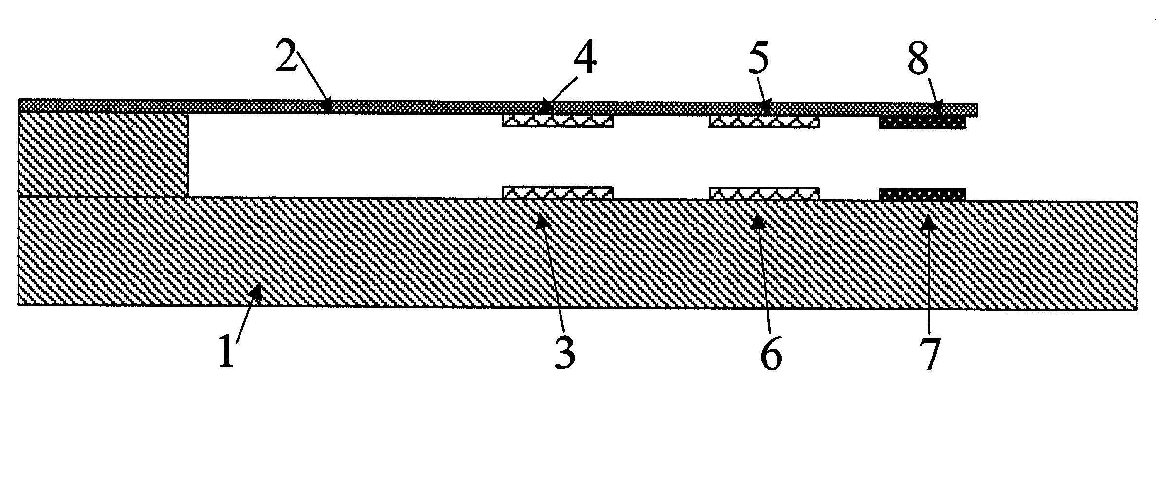
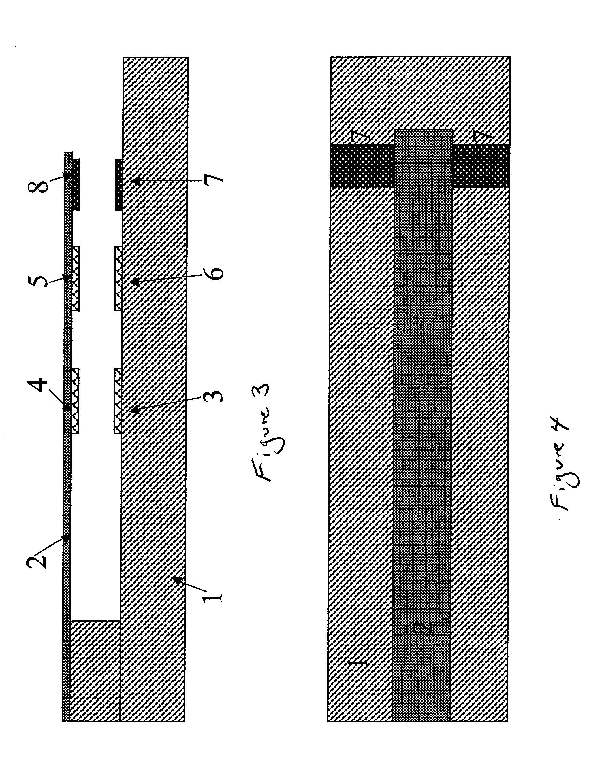
[0026] FIGS. 3-7 illustrate a preferred embodiment of the present invention.

[0027] In FIGS. 3 and 4, a substrate 1 is provided with a MEMS cantilever 2, top and bottom electrodes 3,4 for measuring capacitance, top and bottom control electrodes 5,6 for enabling MEMS movement, interrupted RF line 7, conductive contact 8 for the RF line. Except for the presence of the electrodes 3,4, the MEMS switch of FIGS. 3 and 4 is a well known cantilever type MEMS switch. Alternatively, instead of the additional set of electrodes 3,4 for measuring capacitance, the control electrodes 5,6 are used for both applying the control voltage and measuring the capacitance. However, for the purposes of simplicity in illustrating the principle of operation, the separate pair of electrodes 3,4 is discussed in the present invention. The movable part of the MEMS switch (FIGS. 3, 4) includes the cantilever 2, the electrodes 4,5 and the contact 8.

[0028] FIG. 6 shows a preferred embodiment for the voltage control s...


PUM


Abstract

A switch arrangement includes a MEMS switch connected to a voltage supply system. The MEMS switch has a mechanical resonant frequency. The voltage supply system has a capability for supplying a voltage with a frequency corresponding to the mechanical resonant frequency of the switch. A method includes providing a MEMS switch including a movable part which has a mechanical resonant frequency, and then supplying an AC voltage to the movable part. The AC voltage has a frequency corresponding to the mechanical resonant frequency of the movable part.

Description

[0001] 1. Field of the Invention[0002] The present invention relates to electrical switches and, more particularly, to micro-electrical mechanical system (MEM or MEMS) switches.[0003] 2. Description of the Related Art[0004] Various micro-electrical mechanical system switches, methods of manufacture and operation are known. See, for example, U.S. Pat. Nos. 5,578,976, "Micro Electromechanical RF Switch, Jun J. Yao, Nov. 26, 1996; U.S. Pat. No. 6,100,477, "Recessed Etch RF Micro-Electromechanical Switch", John Neal Randall, et al., Aug. 8, 2000; U.S. Pat. No. 6,127,744, "Method And Apparatus For An Improved Micro-Electrical Mechanical Switch", Robert D. Streeter, et al., Oct. 3, 2000; U.S. Pat. No. 6,160,230, "Method And Apparatus For An Improved Single Pole Double Throw Micro-Electrical Mechanical Switch", Lee A. McMillan, et al., Dec. 12, 2000; and U.S. Pat. No. 6,229,683, "High Voltage Micromachined Electrostatic Switch," Scott Halden Goodwin-Johansson, May 8, 2001, which are all in...

Claims


Application Information

Patent Timeline
Patent Type & Authority Applications(United States)
IPC IPC(8): H01H59/00H01P1/12
CPCH01H59/0009H01H2059/0036H01H2059/0063H01G5/40H01G5/16H01G5/18H01P1/127
Inventor NIKITIN, VLADIMIR
Owner GLOBALFOUNDRIES US INC
Why Eureka
Try Eureka