Fiber optic LED light

a technology of led light and fiber optics, applied in the direction of instruments, thin material processing, paper and paper, etc., can solve the problems of lack of water resistance, lack of secure retention, insufficient structure of led or led's connected to light guides, etc., to reduce, minimize and/or essentially eliminate the above-mentioned inadequacies

Inactive Publication Date: 2003-05-15
LUMENYTE INT
View PDF16 Cites 24 Cited by
  • Summary
  • Abstract
  • Description
  • Claims
  • Application Information

AI Technical Summary

Benefits of technology

[0006] In one aspect of the invention, the optical conduit is inserted into a threaded bore or cavity at one end of the connector. The threads inside the bore tap or form complementary intermeshing threads in the softer outer circumferential surface of the optical fiber, or bundle of fibers, as the connector is twisted or screwed onto one end of the light guide, thereby providing a secure union between the light conduit and the connector, as well as providing a seal against penetration of gas, liquid or small solid particulates into the region of the LED positioned within the connector. Preferably, to enhance the security of the union and the seal, the threaded bore or cavity is slightly tapered so as to narrow slightly along its length from its opening at one end of the connector extending toward the middle of the connector.
[0007] Alternatively, in another aspect of the invention, one or more "O" rings made of a flexible material, suitable for the particular environmental use of a specific fiber optic, are inserted into recesses positioned in the connector bore in which the fiber optic is to be inserted. The O-ring functions to provide a liquid or gas resistant seal, and also functions to assist in securely retaining the light guide within the connector. The outer diameter of the O-ring, or rings, is slightly larger than the interior diameter of the connector, thereby permitting it to be fitted into a recess, or channel on the interior of the connector. Also, the inside diameter of the O-ring, or rings is preferably slightly less than the outer diameter of the light guide, or bundle of light guides, thereby providing for securely gripping the light guide, or light guides, as well as providing a barrier resistant to penetration of any solid (such as very small particulate matter), liquid or gas that contacts the O-rings or ring. Thus, the chamber or bore within which the LED or LED's is placed, remains free of contaminants.
[0009] The electrical structures of the present invention also may be of various physical sizes and of various electrical capacities, such as to accommodate various voltage and current requirements, by using conventional resistors, wires and power sources. Typically, the resistor(s) is / are placed within the connector unit and potted, in a conventional fashion to protect the circuitry from damage and to help retain the LED. The choice of the value of the particular resistor(s) is within the skill of a person of ordinary skill in this field, with the resistor value chosen to convert the voltage from that of the input power supply, to the voltage at which the particular LED(s) is / are designed to operate. Wiring and power supply technology for use with LED lighting systems is well known. The structures used in the present invention can be adapted for specific resistors and other specific electrical components within the system in a conventional fashion, to accommodate a particular end use application.
[0019] In a first embodiment, a channel 50 is provided in the wall of the tube 46 near the first end 52, as shown in FIG. 1. The channel 50 extends circumferentially and has an outer diameter slightly greater than the outer diameter of the cavity 48. The channel 50 is sized and adapted to receive a conventional O-ring 56, as shown in FIG. 1. The O-ring 56 is conventional, and its material of manufacture is selected to accommodate the environment of use of the LED fiber optic light 20, as well as to provide the resilient, sealing function of an O-ring. The O-ring 56 is also, preferably, chosen to have an outer diameter slightly greater than the outer diameter of the channel 50. The O-ring 56 is also chosen to have an inner diameter slightly less than the inner diameter of the chamber 48, as well as slightly less than the outer diameter of the fiber optic light guide 22. Choice of each specific diameter is made in accordance with known principles, and is chosen so as to provide for a secure fit of the light guide 22 within the chamber 48, as well as to provide for maintaining a barrier between that portion of the chamber 48 interior to the O-ring and that part of the chamber 48 on the side of opening 52.
[0022] With reference to FIG. 2, the second embodiment of the present invention includes a light guide, LED light source and tubular connector as shown in FIG. 1, with like components bearing like reference numerals, and, additionally, a second O-ring channel and second O-ring. Thus, a second channel 68 is shown in FIG. 2, having the same structural features as first channel 50, except that second channel 68 is positioned adjacent to and closer to end 54 of cavity 48 than is the first O-ring channel 50. Second o-ring channel 68 is also shown with O-ring 70 in place. The second, or double O-ring structure of the FIG. 2 embodiment provides for an increased degree of securing or retaining the light guide 22 within the cavity 48, as well as providing for an increased strength barrier between the outside environment of use and the inner region chamber or cavity 48, i.e., that region near the LED 36.

Problems solved by technology

However, the structures by which the LED, or LED's are connected to the light guides have been inadequate.
By way of example, the inadequacies include lack of secure retention of the light guide to the light source, lack of water resistance at the point of connection, poor dissipation of heat generated by the light source and difficulty with removal and replacement of the LED light source.

Method used


Image

  • Fiber optic LED light
  • Fiber optic LED light
  • Fiber optic LED light

Examples


example 2

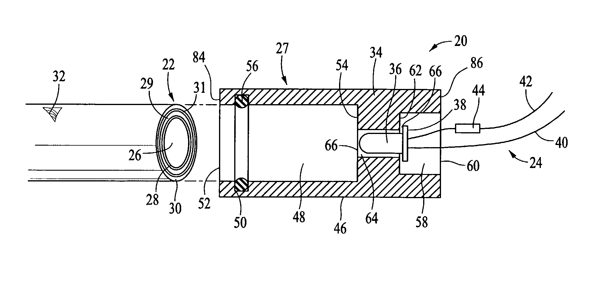
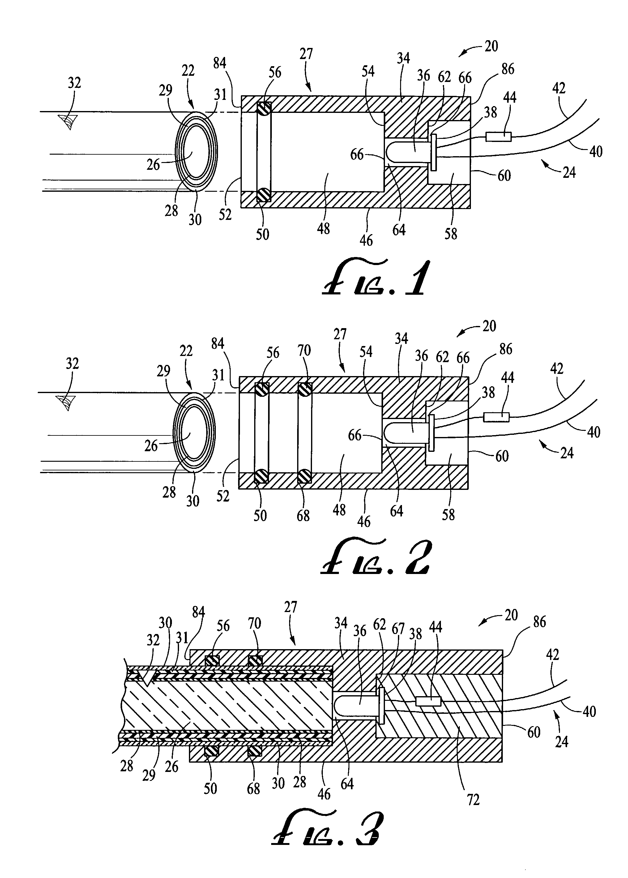
[0028] In a second example, a second solid cylindrical aluminum bar was machined into a connector, as shown in FIG. 1, except that two indents, or O-ring channels were machined into the bar, as illustrated in FIG. 2. All components of the Example 2 embodiment were the same as described above with respect to Example 1, except for the double O-ring structure and that the LED assembly was not potted into chamber 58. The fiber optic 22 was inserted into the chamber 48, butted up against end wall 54 and thereafter pulled and manipulated to determine its relative stability. When pulled and so manipulated, the light guide 22 was substantially more firmly secured within the cavity 48 than was the light guide secured by the single O-ring structure of Example 1. The double O-ring configuration of the present invention is preferable compared to the single O-ring embodiment.

example 3

[0029] In a third example, a hot bonding material, obtained from R. S. Hughes Company was used as the potting material. The hot melt bonding material, Hughes part number 3747PG is sold as its "3M Jet-Melt.TM." bonding material. While both the silicon as well as the hot melt bonding material were useful for the present invention, the preferred potting material is the hot melt bonding material sold as "3M Jet-Melt".

example 4 , 5

EXAMPLE 4, 5, AND 6

[0030] As Examples 4, 5, and 6, ABS, PVC and polycarbonate plastic materials are believed to be useful in the construction of the connector used in the present invention. This belief is based on well known properties for those materials in that they possess sufficient structural rigidity to function as a supporting connector, have the ability to dissipate heat sufficiently, and can be manufactured into appropriate shapes in a cost-effective manner.


PUM

PropertyMeasurementUnit
lengthaaaaaaaaaa
outer diameteraaaaaaaaaa
inner diameteraaaaaaaaaa

Abstract

An LED coupled to a large core plastic optical fiber light guide with a tubular connector having a first bore into which the light guide is inserted, a second bore into which the LED and its attached wires are inserted and a third bore adjacent to the first bore, extending between the first and second bores and into which the LED is positioned so that when illuminated the LED transmits light into the guide with the first bore. The connector includes helical threads formed in the first bore into which the guide is threaded to securely retain the guide within the first bore and which form a seal to prevent contaminants from entering the region in the first bore adjacent the LED. Alternatively, the connector includes one or more internal channels extruding around the inner periphery of the bore and into which one or more O-rings are positioned so that the guide is securely retained within the first bore and that a barrier is formed to prevent contaminants from entering the region in the first bore adjacent the LED. It is emphasized that this abstract is provided to comply with the rules requiring an abstract that will allow a searcher or other reader to quickly ascertain the subject matter of the technical disclosure. It is submitted with the understanding that it will not be used to interpret or limit the scope of the claims.

Description

[0001] This application claims the benefit of U.S. Provisional Application Serial No. 60 / 350,675, filed Nov. 13, 2001, which is incorporated herein by reference.[0002] The present invention relates to improvements in the field of fiber optic lighting in which the light source is one or more light emitting diodes (LED) that in turn are connected to a source of electrical power, a light guide or light guides, such as for example, large core plastic fiber optical conduit, as well as acrylic rods, with a connector into which the light guide and LED are placed so that the LED light source is connected to the light guide.[0003] In the field of large core plastic fiber optical conduit technology light in the visible spectrum is transmitted along a light transmitting form or guide that includes at least a light transmitting core and a cladding. This form is also typically referred to as a fiber optic, conduit, light guide, light form, or simply as an "optic". The transmitted light may, in s...

Claims


Application Information

Patent Timeline
Patent Type & Authority Applications(United States)
IPC IPC(8): G02B6/36G02B6/38G02B6/42
CPCG02B6/02033G02B6/3644G02B6/3833Y10T428/2929G02B6/4202G02B6/4292G02B6/4298G02B6/3855
Inventor ROBBINS, PAUL E.
Owner LUMENYTE INT
Why Eureka
Try Eureka