Radial pump

Inactive Publication Date: 2003-05-29
TCG UNITECH AKTIENGES
View PDF3 Cites 11 Cited by
  • Summary
  • Abstract
  • Description
  • Claims
  • Application Information

AI Technical Summary

Benefits of technology

0017] To permit external control of the flow volume handled by the radial-flow pump, it will be a

Problems solved by technology

At high speeds, however, the Coriolis forces of the coolant flow will cause a deformat

Method used


Image

  • Radial pump
  • Radial pump
  • Radial pump

Examples


Embodiment Construction

with reference to the enclosed drawings.

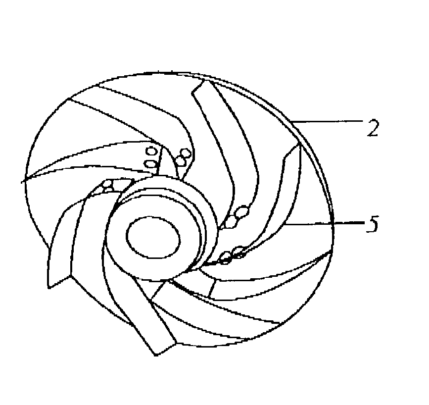
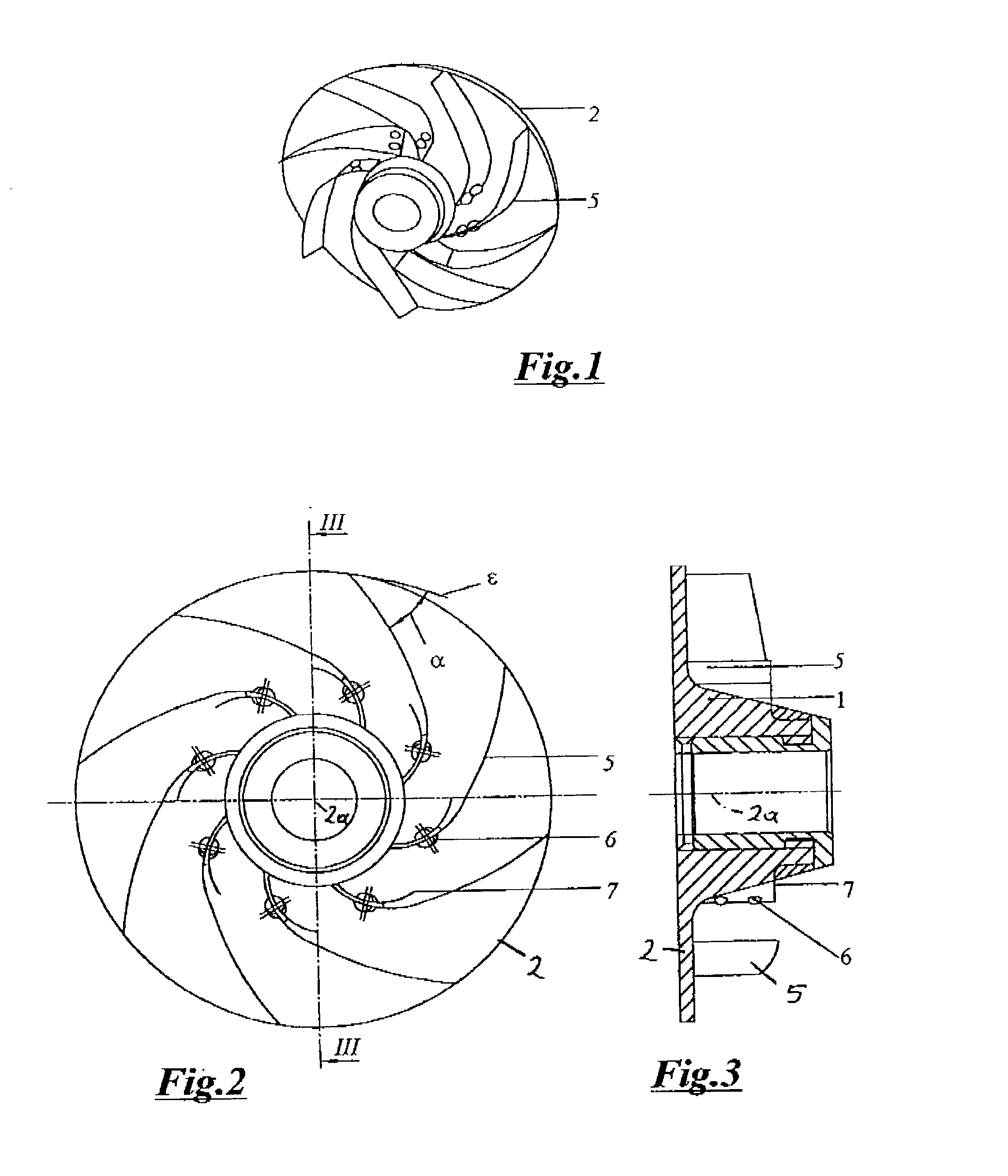
[0019] FIG. 1 shows an impeller of a radial-flow pump according to the invention, in a first variant, in an oblique view,

[0020] FIG. 2 is a view of the impeller from above,

[0021] FIG. 3 shows the impeller in a section along line III-III in FIG. 2,

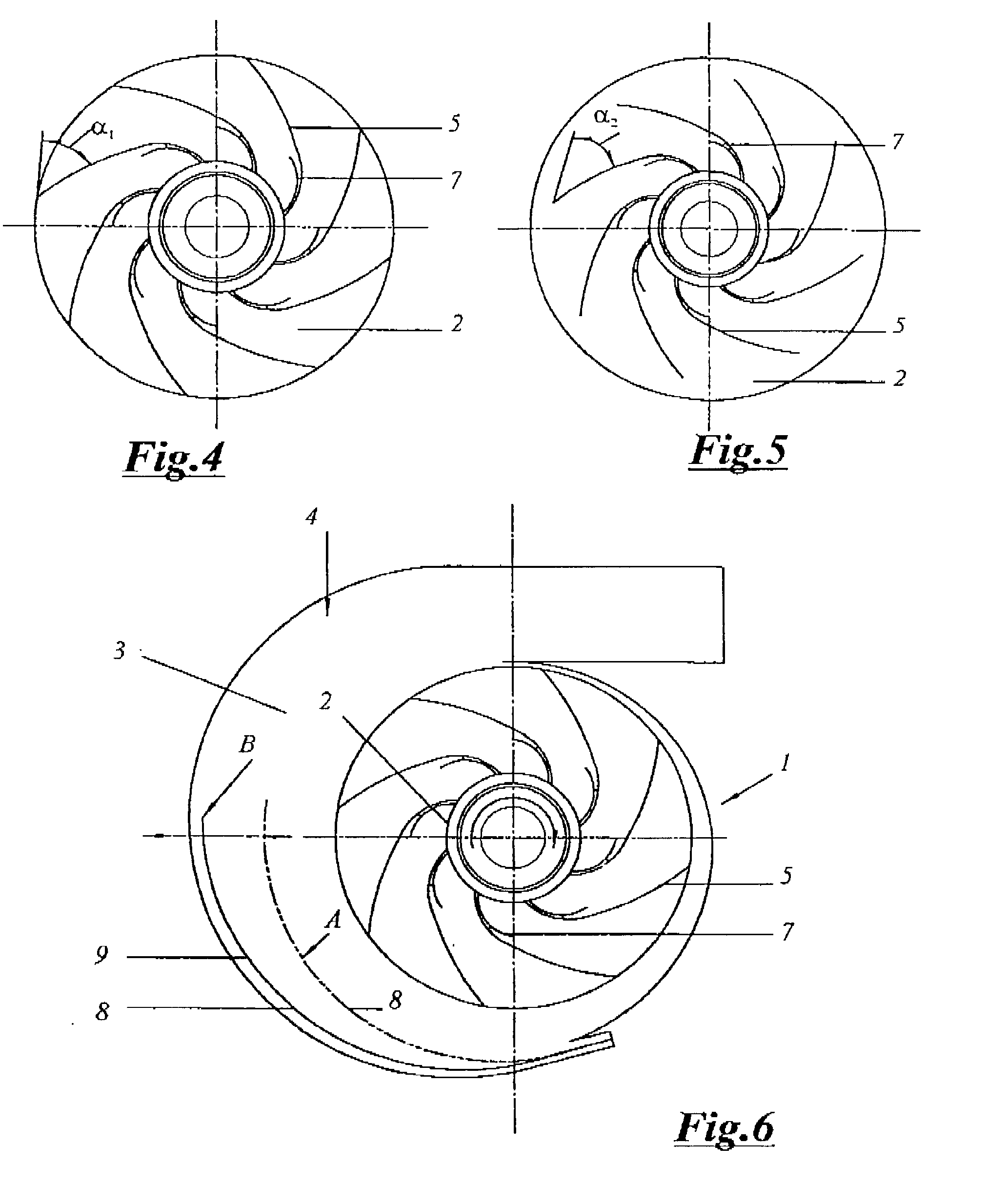
[0022] FIG. 4 shows the impeller with the impeller vanes being in a first position,

[0023] FIG. 5 shows the impeller with the impeller vanes being in a second position,

[0024] FIG. 6 shows the radial-flow pump with the directing device,

[0025] FIG. 7 shows an impeller of a radial-flow pump according to the invention, in a second variant, in a view from above,

[0026] FIG. 8 is an oblique view of this impeller,

[0027] FIG. 9 shows an impeller of a radial-flow pump according to the invention, in a third variant,

[0028] FIG. 10 is a characteristic diagram of the radial-flow pump.

[0029] Parts of identical function bear identical reference numerals in all figures.

[0030] The radial-flow pump 1 is provided with an ...


PUM


Abstract

This invention relates to a radial-flow pump (1), and especially a coolant pump for an internal combustion engine, comprising an impeller (2) provided with vanes (5) and a directing device (4) including at least one temperature- and/or speed-sensitive element for temperature-dependent control of the coolant flow, where at least one impeller vane (5) and/or the directing device (4) is configured as a speed-sensitive element. In order to increase efficiency, the proposal is put forward that the impeller vanes (5) should be elastically deformable by Coriolis forces of the coolant flow, the discharge angles (alpha), which are preferably defined between impeller vanes (5) and impeller tangential planes (epsi), decreasing with an increase in speed.

Description

[0001] This invention relates to a radial-flow pump, and especially a coolant pump for an internal combustion engine, comprising an impeller provided with vanes and a directing device including at least one temperature- and / or speed-sensitive element for temperature-dependent control of the coolant flow, at least one impeller vane and / or the directing device being configured as a speed-sensitive element.[0002] Coolant pumps for use with engines of large passenger cars are often required to handle considerable flow volumes even at low engine speeds. As a consequence extremely large volumes are delivered at maximum speed, which in turn will lead to unduly high pressures in the coolant circulation system. Short circuits to reduce the coolant volume passing through the engine cooling system must have large cross-sections and will inevitably result in power losses.DESCRIPTION OF THE PRIOR ART[0003] Publication DE 37 09 231 A1 describes an impeller made of an extendible elastic material, ...

Claims


Application Information

Patent Timeline
IPC IPC(8): F04D15/00
CPCF04D15/0027Y10S416/50F04D15/0038F04D29/247
Inventor PREINFALK, MARKUSKLAUS, HEINZATSCHREITER, FRITZ
Owner TCG UNITECH AKTIENGES
Why Eureka
Try Eureka