Load carrying assembly

a technology for carrying parts and parts, applied in the field of load carrying parts, can solve the problems of prone to tearing or fraying, less comfortable wearing, and high cost, and achieve the effects of convenient formation, convenient cutting, and no corrosion

Inactive Publication Date: 2003-06-05
MARSHALL PETER ALAN
View PDF16 Cites 28 Cited by
  • Summary
  • Abstract
  • Description
  • Claims
  • Application Information

AI Technical Summary

Benefits of technology

0013] In another form, the shank of a stud may not have an enlarged head but be adapted to take a tight-fitting push-on cap or retainer that is difficult to remove when once forced onto the shank. For this purpose, the shank may be formed with a plurality of peripheral grooves--perhaps formed with a barb or wedge like shape--that allow a ring-like retainer to be pushed rearward on the shank to clamp the material of the pouch to the front face of the panel. The studs can be conveniently formed by upsetting from metal rod or by injection molding from inexpensive plastics material. The use of plastics material is preferred because it is cheap, will not corrode and can be easily cut using clippers or the like to remove a pouch from the panel, when desired.

Problems solved by technology

The latter materials are likely to be less comfortable to wear, cost more because of the need for the perforation step and may be prone to tearing or fraying.

Method used


Image

  • Load carrying assembly
  • Load carrying assembly
  • Load carrying assembly

Examples


Embodiment Construction

[0017] Having portrayed the nature of the present invention, a particular example will now be described with reference to the accompanying drawings. However, those skilled in the art will appreciate that many variations and modifications can be made to the example without departing from the scope of the invention as outlined above. In the accompanying drawings:

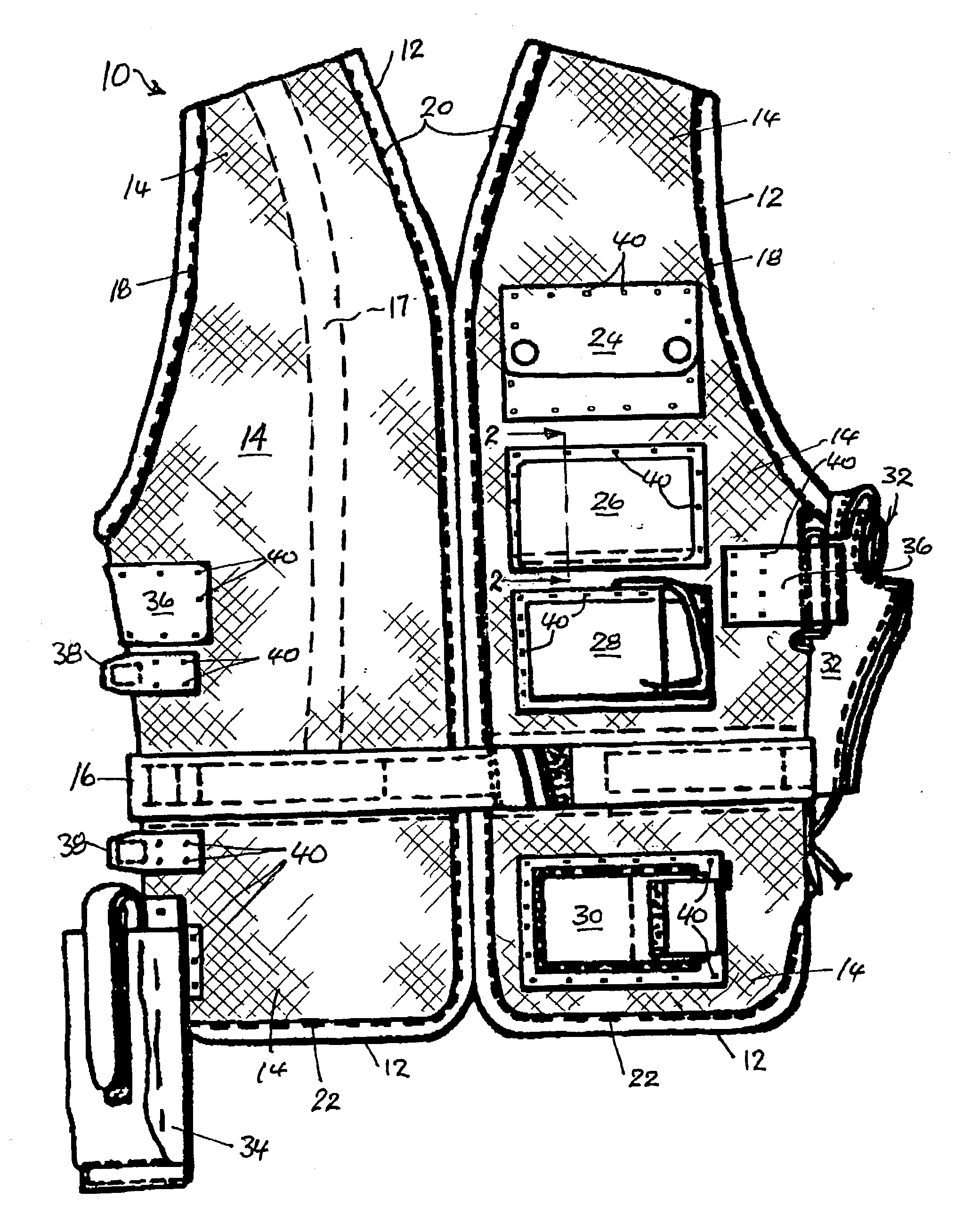
[0018] FIG. 1 is a front elevation of a vest-like garment having load-carrying pouches attached thereto.

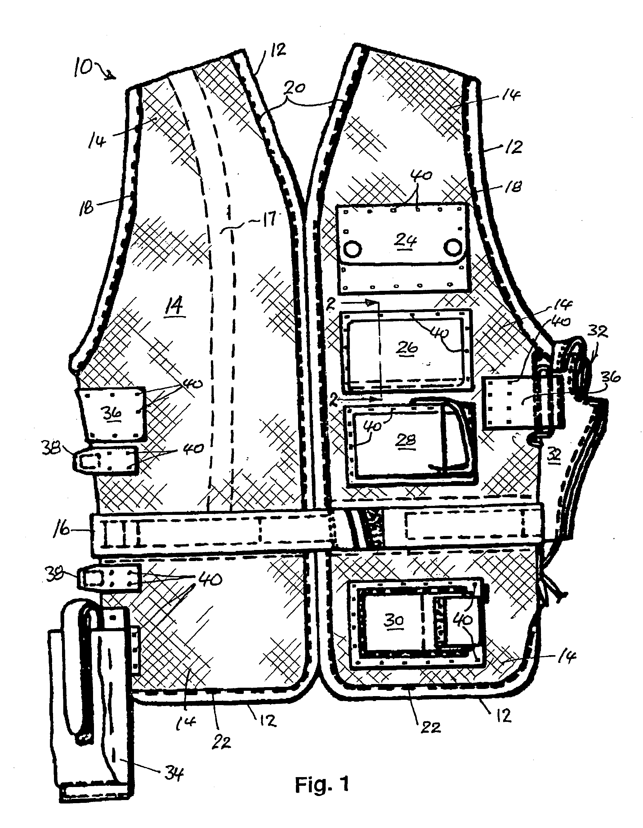
[0019] FIG. 2 is a sectional end elevation of the vest and portion of a pouch taken on section line 2-2 of FIG. 1, FIG. 2A being an enlarged view of a stud fastener.

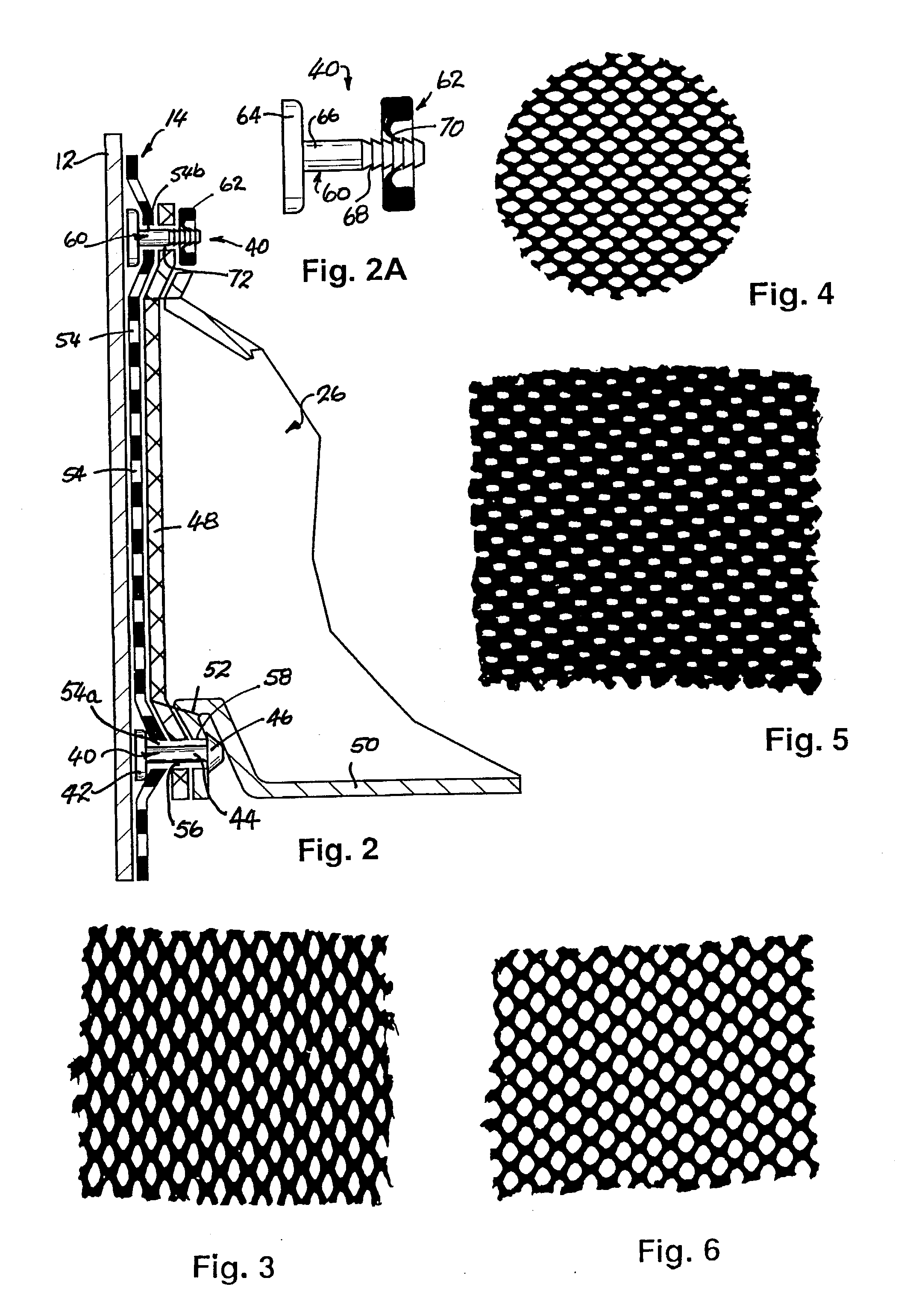
[0020] FIGS. 3 to 6 are representations of various forms of woven mesh suitable for use with the panels and pouches of the vest of FIG. 1.

[0021] With reference to FIGS. 1 and 2, the chosen example of the application of the principles of the present invention is a vest 10 suitable for use by military or paramilitary personnel, or by hunters and fishermen, or by tr...


PUM


Abstract

A load-carrying assembly (10) [FIG. 2] is disclosed comprising a panel (14) having a grid of holes (54) formed therein and at least one load-carrying pouch (26) attached to the panel by means of stud-like fasteners (40, 41) that pass through the holes (54) and through perforations (56, 72) formed in the pouch (26). The panel (14) is preferably formed from a woven textile mesh in which the total area of the holes is less than 75% of the area of the panel, in which the mesh is less extensible in the vertical (load-carrying) direction than in the lateral or horizontal direction, and in which the studs are preferably a close fit in the holes of the mesh and the perforations of the pouch.

Description

[0001] This invention relates to load carrying assemblies suitable for use in supporting loads from garments, packs or the like. It also relates to load-supporting garments, saddles, packs and the like or to portions thereof.[0002] The load carrying assemblies and the garments or packs of the invention will be of use to armed service personnel, sports persons, medical and veterinarian field officers, fishermen, hikers, tradesmen and many others who need to carry small items of equipment in a manner convenient to access. The load carrying assemblies may also be in the form of saddles other coverings used with animals, motorbikes and other machines. They may be in the form of kits for tools, first aid or emergency equipment or the like not designed to be worn or supported by people, animals or machines. Generally, the load items will be carried in or by pouches, pockets, suspension loops, holsters, specially formed sockets or the like containers or supports, which are secured to the g...

Claims


Application Information

Patent Timeline
Patent Type & Authority Applications(United States)
IPC IPC(8): A41D13/00B25H3/00B25H3/04
CPCA41D13/0012B25H3/04B25H3/00
Inventor MARSHALL, PETER ALAN
Owner MARSHALL PETER ALAN
Why Eureka
Try Eureka