
Environmental control method and system

a technology of environmental control and control method, applied in the direction of electrical digital data processing, structural/machine measurement, instruments, etc., can solve the problems of limited user or occupant control, restricted access permissions, and limited control of user or occupan

Inactive Publication Date: 2012-11-22
CALE RICHARD JOHN +1
View PDF13 Cites 33 Cited by
  • Summary
  • Abstract
  • Description
  • Claims
  • Application Information

AI Technical Summary

Benefits of technology

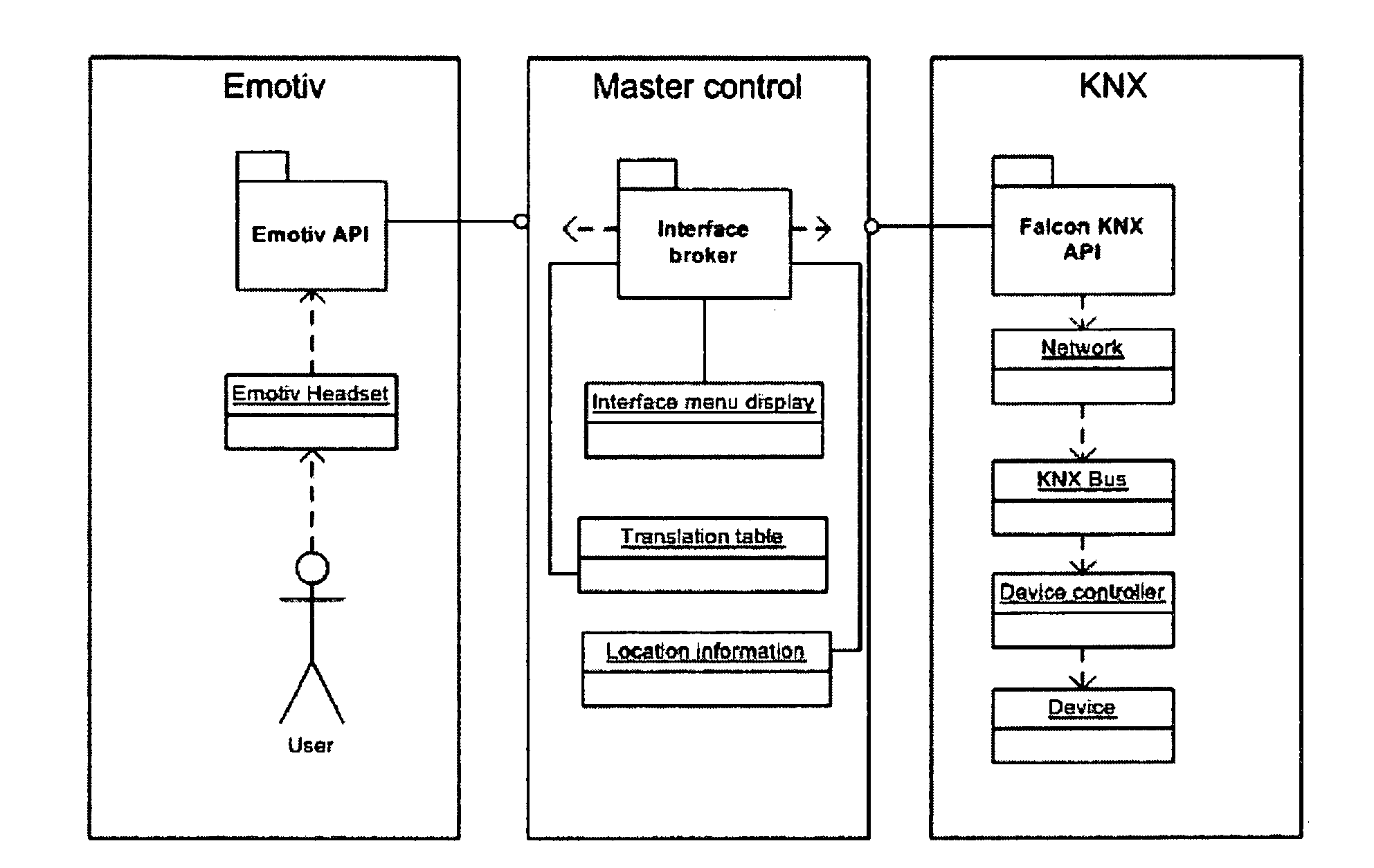
[0042]In a preferred embodiment, the peripheral devices, network or networks, and controller or controllers employed by the present invention may be implemented so as to conform to the KNX™ smart building management protocol. The KNX™ protocol provides an effective mechanism where the operation of a building's peripheral devices can be managed efficiently, and also allows a wide range of peripheral devices sourced from many different manufactures to be interfaced together and work effectively within a single structure.
[0050]In a preferred embodiment, a user input system may be formed by an Emotive™ neural signal detection headset. The Emotive™ headset provides a convenient form of user input system which does not require the scalp of the user be shaved or otherwise prepared prior to the headset being employed. The Emotive™ headset and its associated signal processing systems can allow an intelligent determination to be made as to the identity of a specific command consciously issued by a user, or the emotional state or condition of the user.
[0060]Preferably, the interface provided by the present invention may also implement or facilitate a hierarchal command menu system to be navigated by a user to issue a particular command. For example, in a further preferred embodiment a hierarchal based menu system may be provided which gives a user a choice of a maximum of four options to select a command from at any one point in time. Each of these maximum of four options can be associated with or represented by a particular direction—being forward, back, left, or right (for example), to allow a user to intuitively select a particular command. Those skilled in the art should appreciate that other types of menu, user interface, or interaction systems may however be implemented in conjunction with the present invention if required.
[0066]In a preferred embodiment, the present invention may include at least one user position detection device or system. A user position detection device can be employed to provide the invention with information as to the specific location within a structure which a user occupies, thereby allowing the invention to tailor the commands or options open to a user. For example, in some instances a hierarchal menu of command options namely available to a user can be restricted to remove invalid commands which cannot be issued in relation to the user's current location.

Problems solved by technology

Very limited user or occupant control can be provided by push buttons or dial based manual override switches.
An issue identified with respect to intelligent buildings is the degree of control afforded to the occupants of the building with respect to their environment.
Furthermore, access permissions are usually restricted to a small number of persons authorised to modify the behaviour of the system.
This is potentially an issue for occupants who must live with the “one size fits all” policy decisions of the building automation system.
Changes in the behaviour of the automation system are difficult and slow to effect, and cannot easily be made with respect to the requirements of one particular user or a small localised area within an intelligent building.
Existing building automation systems simply focus on the control of lighting and air conditioning systems, and do not necessarily interface with or allow fully control of additional components or equipment incorporated within a smart building.
Furthermore, the behaviours of building automation systems are not necessarily driven by the current state or condition of the building's occupants.
These building automation systems are unaware of any physical distress experienced by their occupants or of the emotional state of building occupants and hence are unable to tailor the environment they provide in light of same.
This approach can cause difficulties for persons who forget their access codes or lose the authorisation token provided to them—effectively locking them out of the structure which they have valid access rights to.

Method used


Image

  • Environmental control method and system
  • Environmental control method and system
  • Environmental control method and system

Examples


Embodiment Construction

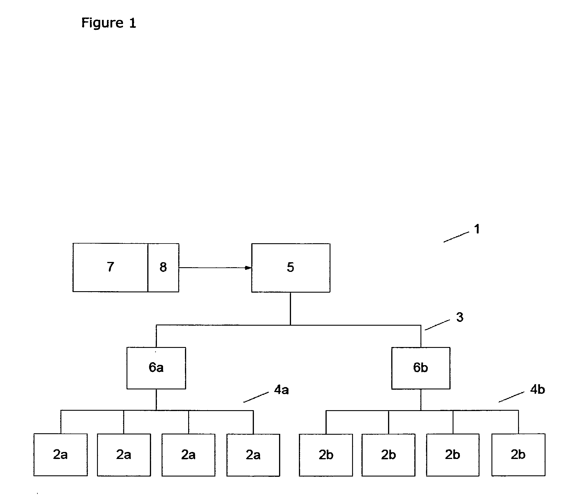
[0075]FIG. 1 shows a block schematic diagram of an environmental control system implemented in accordance with a preferred embodiment of the present invention.

[0076]In the embodiment shown with respect to FIG. 1, an environment management system (1) for an office block is shown. The environment management system (1) incorporates a number of peripheral devices (2a, 2b) where the operation of each of these peripheral devices modifies the environment of at least one region within the structure.

[0077]In the embodiment shown the peripheral devices (2a) are formed by independent lighting components distributed throughout the various floors and rooms of the office structure. The second set of peripheral devices (2b) are formed by a range of air conditioning or climate control components. These components (2b) can modify the temperature and climate within individual or localised regions of the office structure.

[0078]The environment management system (1) also incorporates a primary network (...


PUM


Abstract

The invention relates to an environment management system method and apparatus used to manage the environment within a structure. When implemented within a system the invention includes a plurality of peripheral devices distributed within the structure where operation of a peripheral device modifies the environment of at least one region of the structure associated with the peripheral device. The system also includes at least one network which connects the plurality of devices, and at least one controller arranged to receive signals from one or more peripheral device and to transmit a command to one or more peripheral devices using this network. The system of the invention also includes a user input system interfaced with the at least one controller where this user input system is arranged to use at least one user neural signal to provide a user command to one or more controllers.

Description

TECHNICAL FIELD[0001]The present invention relates to a method, apparatus and system used to control the environment of a user or occupant of a structure. Preferably, the invention may be employed to allow a user to interface with a control system of an intelligent building or automated structure by way of neural electrical activity signals.BACKGROUND TO THE INVENTION[0002]Building automation systems have been developed which employ computer controlled networks of environmental control peripherals. These peripheral devices can be provided through lighting, air conditioning or climate control components as well as mechanical elements or components. Such a control system and associated peripheral devices form what can be known as an intelligent building. Intelligent buildings are networked with one or more bus systems to allow data to be forwarded to controller components from sensors or environmental control devices, and for commands issued by controllers to be actuated by environmen...

Claims


Application Information

Patent Timeline
Patent Type & Authority Applications(United States)
IPC IPC(8): G05B15/02G05D23/19
CPCG06F3/015G05B15/02
Inventor CALE, RICHARD JOHNKYRIAKOU, MARY-ANNETULLY, FRASER R.
Owner CALE RICHARD JOHN
Learn More