Impingment jet aeration

a technology of impingement jet and aerator, which is applied in the direction of machine/engine, carburetor air, separation process, etc., can solve the problems of increasing the use of impingement jet aerators, poor overall efficiency, and increasing the amount of oxygen transfer

Inactive Publication Date: 2003-06-05
KHUDENKO BORIS M
View PDF0 Cites 12 Cited by
  • Summary
  • Abstract
  • Description
  • Claims
  • Application Information

AI Technical Summary

Benefits of technology

[0004] It is also the objective of the present invention to provide a simple, reliable, and inexpensive method of aeration.
[0006] This is a method of water aeration with impingement jet aerator having a bottom, side walls, and at least one jet issue means. The jet aerator is provided in a body of water being aerated. The process steps comprise airlifting water from the body of water into the impingement jet aerator, issuing a jet of lifted water through the jet issue means and impinging the jet into the body of water. A two-step aeration occurs, during the airlifting step and during the jet impinging step, wherein the falling jet entraps air from the ambient air into the water. The effect of oxygen transfer is greater than the additive effect of aeration in these two steps due to an entrapment of some airlifting air bubbles into the jet issuing from the aerator and roughing this jet. A rougher jet having a non-smooth surface is trapping more ambient air into the water body being aerated, thus unexpectedly increasing the oxygen transfer. Additionally, the hydraulic efficiency of low-head (0.5 to 3.0 meters) high-flow airlifts is greater than that of high-flow mechanical pumps, if such pumps are available. Therefore, the overall aeration efficiency is increased using a very simple, reliable, and inexpensive device. In many cases multiple aerators can be operated with a single blower for airlifting, while one pump per one aerator is normally required for a pump-jet arrangement.
[0009] The impingement jet aerator can be a float-supported impingement jet aerators, and rigidly supported impingement jet aerators. Rocking and swinging of the float-supported impingement jet aerator can be provided. This further improves air entrapment and the efficiency of aeration. The method provides for entraining at least a portion of airlift air into the jet issuing from the issuing means. Pulsing of the issuing jet can also be provided. For example, by mechanical means, and also by pulsed, on / off, periodic, and nonuniform feeding of the airlifting air. An example of mechanical means can be a flap, a turbine, or a propeller attached to the jet aerator and mechanically deflecting and pulsing the issuing jet.
[0011] The body of the jet aerator can be provided with at least one inclined baffle installed inside. The baffle can be flat, conical, polygonal, or other. Water rotates around such baffles inside the aerator body thus increasing the airlift efficiency and virtually eliminating the splashing effects. These baffles are described in the U.S. Pat. No. 6,220,822 B1.
[0014] Similarly to the device described in the U.S. Pat. No. 4,482,510, the present aerator can be made selfpropelled. Additionally, suction side of the riser can be turned in the direction opposite to that of the issuing jet. Both arrangements increase the capacity of this aerator to mix large volumes of water.

Problems solved by technology

For example, the device described in the above cited patent had been tested and showed very good efficiency of the aerator but a poor overall efficiency due to a mismatch between the recycle pump pressure (more than 3 m) and the required jet aerator head (about 1 m).
This is a significant problem which precluded a wider use of impingement jet aerators.
A rougher jet having a non-smooth surface is trapping more ambient air into the water body being aerated, thus unexpectedly increasing the oxygen transfer.

Method used


Image

  • Impingment jet aeration
  • Impingment jet aeration

Examples


Embodiment Construction

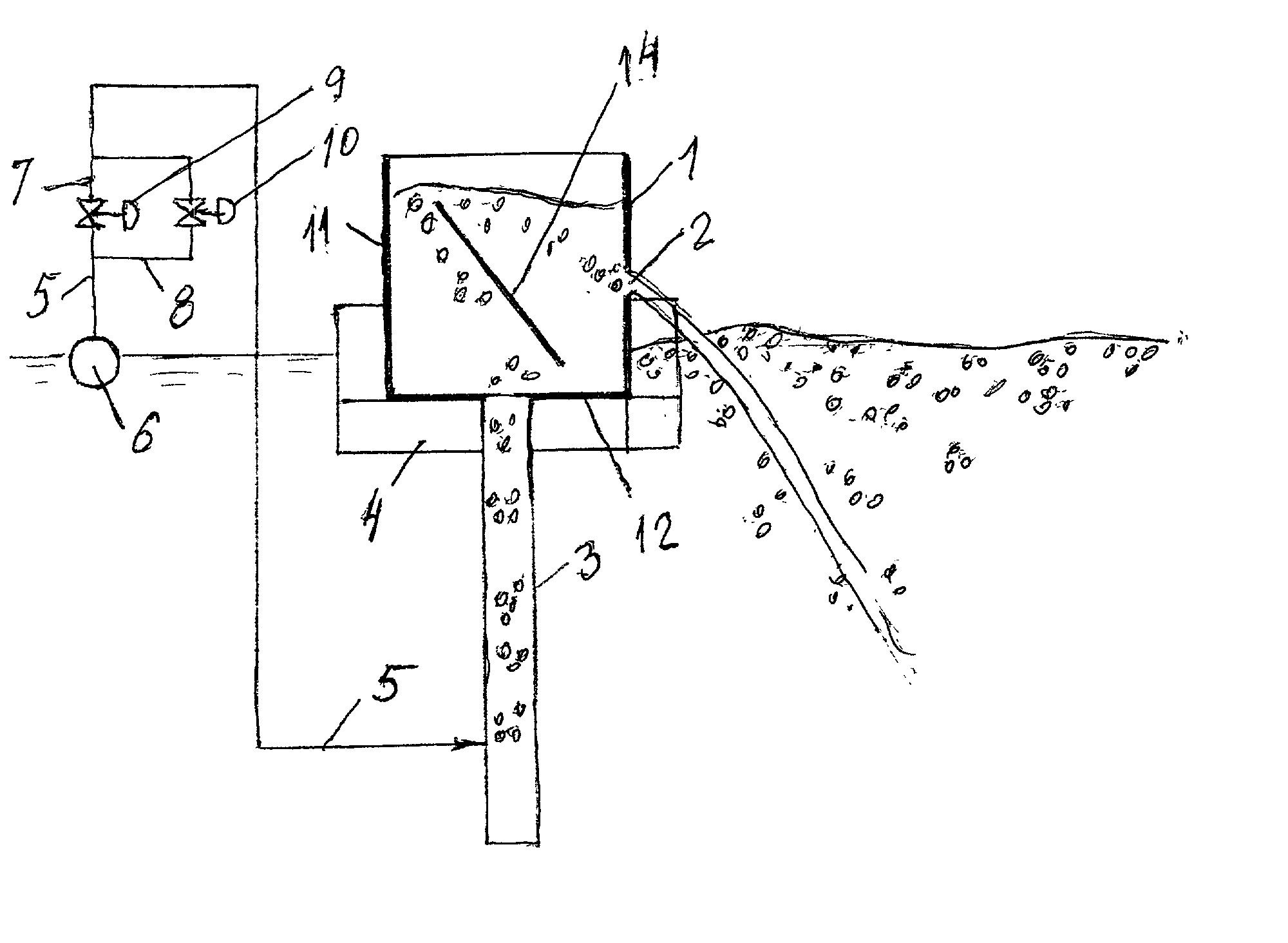
[0017] FIGS. 1 and 2 illustrate an impingement jet aerator consisting of a body 1 with a sidewall 11 and bottom 12, a tooth-shaped orifice 2 in a front wall (more than one orifice in more than one wall can be provided), an optional inclined flow rotating baffle 14, floats 4 supporting the aerator, a riser 3 with air pipe 5 having a flexible portion at the jet aerator, pipe 5 is connected to an air main 6 (a floating pipe 6 is shown in this example). The line 5 has branches 7 and 8 with control valves 9 and 10.

[0018] The aerator is operated as follows. Air is fed in the riser 3 via line 5 when at least one valve 9 or 10 is open. The air lifts the water inside the body of the aerator. If inclined baffle 14 is installed, the contents of the aerator rotate around the baffle. This improves the airlift efficiency and reduces the splashes. Water with some air bubbles enters the orifice 2 and a water jet issue from the aerator 1 into the water body being aerated. The air bubbles roughen the...


PUM

PropertyMeasurementUnit
massaaaaaaaaaa
mixing efficienciesaaaaaaaaaa
pressureaaaaaaaaaa

Abstract

This is an improved impingement jet aeration having steps of airlifting water in the body of the aerator and issuing a water jet into the body of water being aerated, wherein the efficiency of these two steps is greater than the sum of these step. The process is further improved by applying oscillations to the issuing water jet and rocking to a floating version of the aerator. The floating aerator can also be moved over the body of water being aerated. This aerator can also be selfpropelled.

Description

[0001] The present method belongs to aeration of water and wastewater in treatment plants, natural water bodies, man made lakes, and other applications wherein oxygenation, mixing, destratification, deicing, and other actions upon water mass may be required.PRIOR ART[0002] A great many aerators are used in water management systems. They are well known in the art. Impingement jet aerators have been studied first by Gameson in England about fifty years ago, and later by others, including the present writer. For example, U.S. Pat. No. 4,482,510 describes a selfpropelled jet aerator. This patent is made a part of present application by inclusion. Impingement jet aerators per se have very high oxygen transfer and mixing efficiencies at water drops of 0.5 to 3 meters. These efficiencies can be well realized when there is a natural water drop, for example, in oxygen saturation of treated effluents, where a drop between a wastewater treatment plant and a river exists. There have been attemp...

Claims


Application Information

Patent Timeline
Patent Type & Authority Applications(United States)
IPC IPC(8): B01F3/04B01F3/08
CPCB01F3/04517B01F3/04524B01F3/0876B01F3/04744B01F3/0473B01F23/232312B01F23/232311B01F23/23411B01F23/234B01F23/454
Inventor KHUDENKO, BORIS M.
Owner KHUDENKO BORIS M
Why Eureka
Try Eureka