Method for depositing a low k dielectric film (k<3.5) for hard mask application

a dielectric film and hard mask technology, applied in the direction of bulk negative resistance effect devices, semiconductor/solid-state device details, coatings, etc., can solve the problems of difficult etching and patterning of copper, and the inability to etch copper using traditional deposition/etching processes for forming interconnects,

Inactive Publication Date: 2003-06-19
APPLIED MATERIALS INC
View PDF0 Cites 182 Cited by
  • Summary
  • Abstract
  • Description
  • Claims
  • Application Information

AI Technical Summary

Problems solved by technology

One difficulty in using copper in semiconductor devices is that copper is difficult to etch and pattern precisel...

Method used


Image

  • Method for depositing a low k dielectric film (k&lt;3.5) for hard mask application
  • Method for depositing a low k dielectric film (k&lt;3.5) for hard mask application
  • Method for depositing a low k dielectric film (k&lt;3.5) for hard mask application

Examples


Embodiment Construction

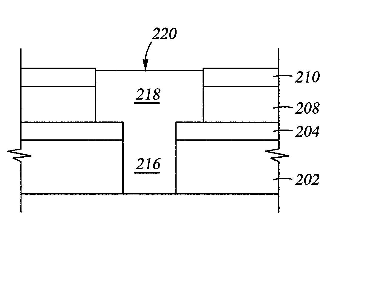
[0043] A silicon oxycarbide hard mask was deposited on a low k dielectric layer, such as SILK.RTM. dielectric coatings available from Dow Chemical Company or Black Diamond.TM. films available from Applied Materials, Inc. of Santa Clara, Calif., by introducing 1,1,3,3-tetramethyldisiloxane into a processing chamber at about 400 mg / min, introducing helium at about 250 sccm into the processing chamber, generating a plasma in the processing chamber by applying 700 watts of RF single frequency energy, maintaining the substrate temperature at about 350.degree. C., and maintaining the chamber pressure at about 8 Torr. The heater spacing was about 500 mils from the substrate surface. Under these conditions, the silicon oxycarbide hard mask was deposited at about 1,825 .ANG. / min.

[0044] The deposited silicon oxycarbide hard mask was examined, and the measured dielectric constant was about 3.3. The hardness of the silicon oxycarbide hard mask was about 1.8 gPa. The leakage current of the silic...


PUM

PropertyMeasurementUnit
Fractionaaaaaaaaaa
Hardnessaaaaaaaaaa

Abstract

A method for depositing a silicon oxycarbide hard mask on a low k dielectric layer is provided. Substrates containing a silicon oxycarbide hard mask on a low k dielectric layer are also disclosed. The silicon oxycarbide hard mask may be formed by a processing gas comprising a siloxane.

Description

[0001] This application claims benefit of U.S. provisional patent application serial No. 60 / 340,615, filed Dec. 14, 2001, entitled "A Method for Depositing Dielectric Materials in Damascene Applications," which is herein incorporated by reference.[0002] 1. Field of the Invention[0003] The present invention generally relates to the fabrication of integrated circuits. More particularly, the invention relates to a process for depositing a hard mask on a dielectric layer and structures which include the hard mask and the dielectric layer.[0004] 2. Description of the Related Art[0005] Semiconductor device geometries have dramatically decreased in size since such devices were first introduced several decades ago. Since then, integrated circuits have generally followed the two year / half-size rule (often called Moore's Law), which means that the number of devices that will fit on a chip doubles every two years. Today's fabrication plants are routinely producing devices having 0.35 .mu.m and...

Claims


Application Information

Patent Timeline
IPC IPC(8): C23C16/30C23C16/40C23C16/56H01L21/311H01L21/312H01L21/316H01L21/768
CPCC23C16/30H01L21/76829C23C16/56H01L21/02126H01L21/02216H01L21/02274H01L21/31138H01L21/31144H01L21/312H01L21/3122H01L21/3127H01L21/31633H01L21/7681H01L21/76826H01L21/76828C23C16/401
Inventor XIA, LI-QUNXU, PINGYANG, LOUISHUANG, TZU-FANGZHU, WEN H.
Owner APPLIED MATERIALS INC
Why Eureka
Try Eureka