Polarization independent thin film optical interference filters

a thin film, optical interference technology, applied in the direction of optics, optical elements, instruments, etc., can solve the problems of limited application of tffs as tunable filters, limited effect of 5% of center wavelength, and state-of-the-art vacuum deposition techniques

Inactive Publication Date: 2003-07-10
CHAMELEON OPTICS HLDG +1
View PDF2 Cites 11 Cited by
  • Summary
  • Abstract
  • Description
  • Claims
  • Application Information

AI Technical Summary

Problems solved by technology

This tuning effect is limited to about 5% of the center wavelength, however, so that the application of TFFs as tunable filters has been limited.
However, state-of-the-art vacuum deposition techniques (how the vast majority of TFF's are fabricated) have a typical random error of 1% for the individual layer thickness.
Thus the fabrication error is 100 times the allowable error!
However, these designs all require numerous layers of arbitrary thickness and thus are not compatible with the interferometric monitoring system necessary for successfully building ultra narrowband bandpass filters for DWDM.
These design methods are achievable with interferometric monitoring system usage, but suffer from other disadvantages.
Adding a HWC thickness to the quarter wave plates in the quarter wave stacks makes the entire filter considerably thicker, which makes it harder to manufacture and subject to greater curvature and strains.
The method will still work if there is more than one intervening layer, but there is generally no advantage to doing so.
Start with filter design which meets normal incidence requirements, but has unacceptable polarization characteristics at higher angles of incidence (AOI).

Method used


Image

  • Polarization independent thin film optical interference filters
  • Polarization independent thin film optical interference filters
  • Polarization independent thin film optical interference filters

Examples


Embodiment Construction

:

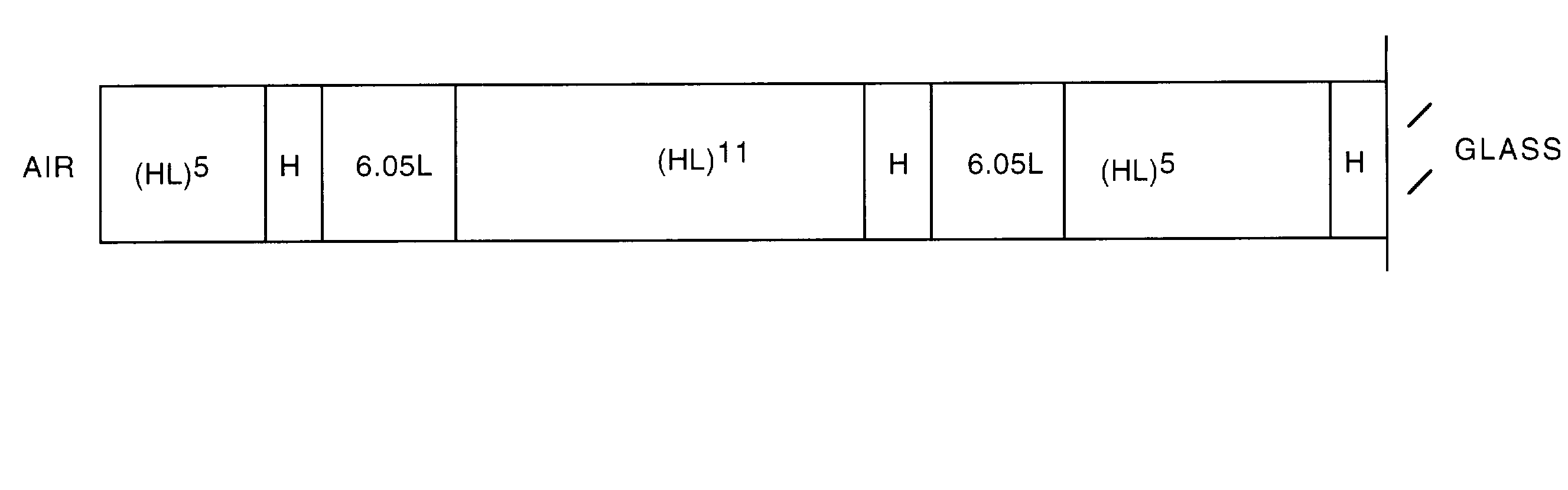
[0074] FIG. 3 is diagram illustrating a filter design according to method (1) of the present invention. Method (1) is as follows:

[0075] Method (1): Add (or subtract) a small increment of thickness to each HWC in a filter, equally.

L H [2mL] H L . . . ->. . . L H [2mL+.DELTA.] H L . . . or

L H [2mL] H L . . . ->. . . L H [2mL-.DELTA.] H L . . .

[0076] for all HWC in the filter.

[0077] This is equivalent to designing the HWC to have a slightly different resonant wavelength then the surrounding QWS's.

[0078] This change directly affects the relative rate at which the S and P-polarization bandpasses angle-tune. To achieve the goal of having the S and P bandpasses tune together with increasing AOI, a low-index HWC is made to be resonant at longer wavelength than the QWS, and a high-index HWC is made to be resonant at a shorter wavelength than the QWS.

[0079] In the example of FIG. 3, the filter prescription is:

[0080] AIR I (HL).sup.5H(6.05L)(HL).sup.11H (6.05L)(HL).sup.5 H I GLASS

[0081] Where...


PUM


Abstract

Design and construction of polarization-independent thin film interference filters is accomplished by applying at least one of the following design rules to an original filter design including quarter wave stacks (QWS) of layers of alternating higher index material (H) and lower index material (L) and half wave cavities (HWC): design rule 1-increasing or decreasing the thicknesses of HWC's in the filter by a small (less than ¼ wavelength) increment; design rule 2-adding small increments (less than ¼ wavelength) to one or more layers and correspondingly subtracting equivalent aggregate increments from one or more adjacent or nearby layers; or design rule 3-replacing HWC's with asymmetric composite HWC's.

Description

[0001] This application claims priority to the following provisional patent applications and incorporates them herein by reference: Ser. No. 60 / 324,168, filed Sep. 21, 2001; Ser. No. 60 / 344,312, filed Dec. 20, 2001; and Ser. No. 60 / 379,888, filed May 13, 2002.[0002] The present invention relates to the design and construction of thin film interference filters, and particularly to filters that are polarization independent.DESCRIPTION OF THE PRIOR ART[0003] Multiple layer thin film optical interference filters are a relative mature technology, in that higher order optical bandpass functions can be tailored at will to diverse applications. Examples are various beamsplitter types, fluorescent microscopy filters, narrow bandpass telecom filters, and telecom gain equalization filters. Most thin film interference filters (TFFs) are used so that the normal vector to the filter surface is nearly parallel (at 0 degrees) to the incident light (designated 0.degree. incidence, or normal incidenc...

Claims


Application Information

Patent Timeline
Patent Type & Authority Applications(United States)
IPC IPC(8): G02B5/28
CPCG02B5/288
Inventor CORMACK, ROBERT H.GOLDBERG, DAVID A.
Owner CHAMELEON OPTICS HLDG
Why Eureka
Try Eureka