Irregular-shape body, reflection sheet and relection-type liquid crystal display element, and production method and production device therefor

a liquid crystal display element and reflection sheet technology, applied in the field of irregular shape body, reflection sheet and relection-type liquid crystal display element, production method and production device therefor, can solve the problems of complex processes, significantly lower visibility, and no conventional technique to easily form a sloped surface of concave/convex shape into a generally triangle shap

Inactive Publication Date: 2003-07-31
JAPAN DISPLAY CENT INC
View PDF10 Cites 81 Cited by
  • Summary
  • Abstract
  • Description
  • Claims
  • Application Information

AI Technical Summary

Problems solved by technology

However, visibility is significantly lower in a dark indoors or during night time.
However, no technique is known conventionally to easily form a sloped surface of the concave/convex shape into a generally triangle shape.
The processes are complicated and there is a challenge associated with productivity.
Consequently, the display screen is significantly dark in a viewing direction of a viewer such as a direction of the regular angle of visibility, which brings about drop in visual quality.
However, in the above-mentioned conventional manufacturing method, the control of the tilt angle works in theory but a desired reflector cannot be manufactured due to too small manufacturing process margins.
More specifically, in practical manufacturing process, a reflector having a desired tilt angle cannot be manufactured due to, for example, an error of a heating temperatu...

Method used


Image

  • Irregular-shape body, reflection sheet and relection-type liquid crystal display element, and production method and production device therefor
  • Irregular-shape body, reflection sheet and relection-type liquid crystal display element, and production method and production device therefor
  • Irregular-shape body, reflection sheet and relection-type liquid crystal display element, and production method and production device therefor

Examples


embodiment 1-1

[0123] (Embodiment 1-1)

[0124] The embodiment 1-1 is characterized in that a reflector has at least two or more regions formed thereon in which convex portions are arranged regularly or recurrently. This configuration provides an effect of making clouring be more invisible.

[0125] For the purpose of facilitating the understanding of the embodiment 1-1, a principle of the embodiment 1-1 is described prior to making description of a specific configuration of the embodiment 1-1.

[0126] [Description of Principle]

[0127] Adjacent convex portions or concave portions are formed so that they have recurrency, i.e., at a constant pitch, when concave / convex shapes are formed on a reflector. The pitch at this time is defined as d1 .mu.m. It is assumed that a white beam is directed to such a reflector at an angle of incidence of -i.sub.0.degree., relative to the axis on which the convex portions are formed, so that they have recurrency. It is observed so that a peak appears at a measured angle repre...

embodiment 1-2

[0147] (Embodiment 1-2)

[0148] FIG. 6 is a perspective view of the reflector according to the embodiment 1-2. A reflector 61 in this embodiment has two different regions, an A region 62 and a B region 63 that are formed thereon with the same pitches of the adjacent convex portions arranged in different directions. The convex portions 14 are formed on the surface of the reflector in the A region 62 at a pitch D1=9 .mu.m. A coordinate axis 64 shown in FIG. 6 is determined so that an angle 66 is 90.degree. between the axis and a straight line 65 corresponding to the direction of arrangement of the convex portions. On the other hand, an azimuth .theta.2 was 30.degree. in this embodiment. The B region has an arrangement corresponding to the arrangement of the convex portions of the A region rotated. Reflection characteristics of the reflector having the above-mentioned configuration were measured, while rotating the measurement device shown in FIG. 3 at right angles to the straight line 6...

embodiment 1-3

[0154] (Embodiment 1-3)

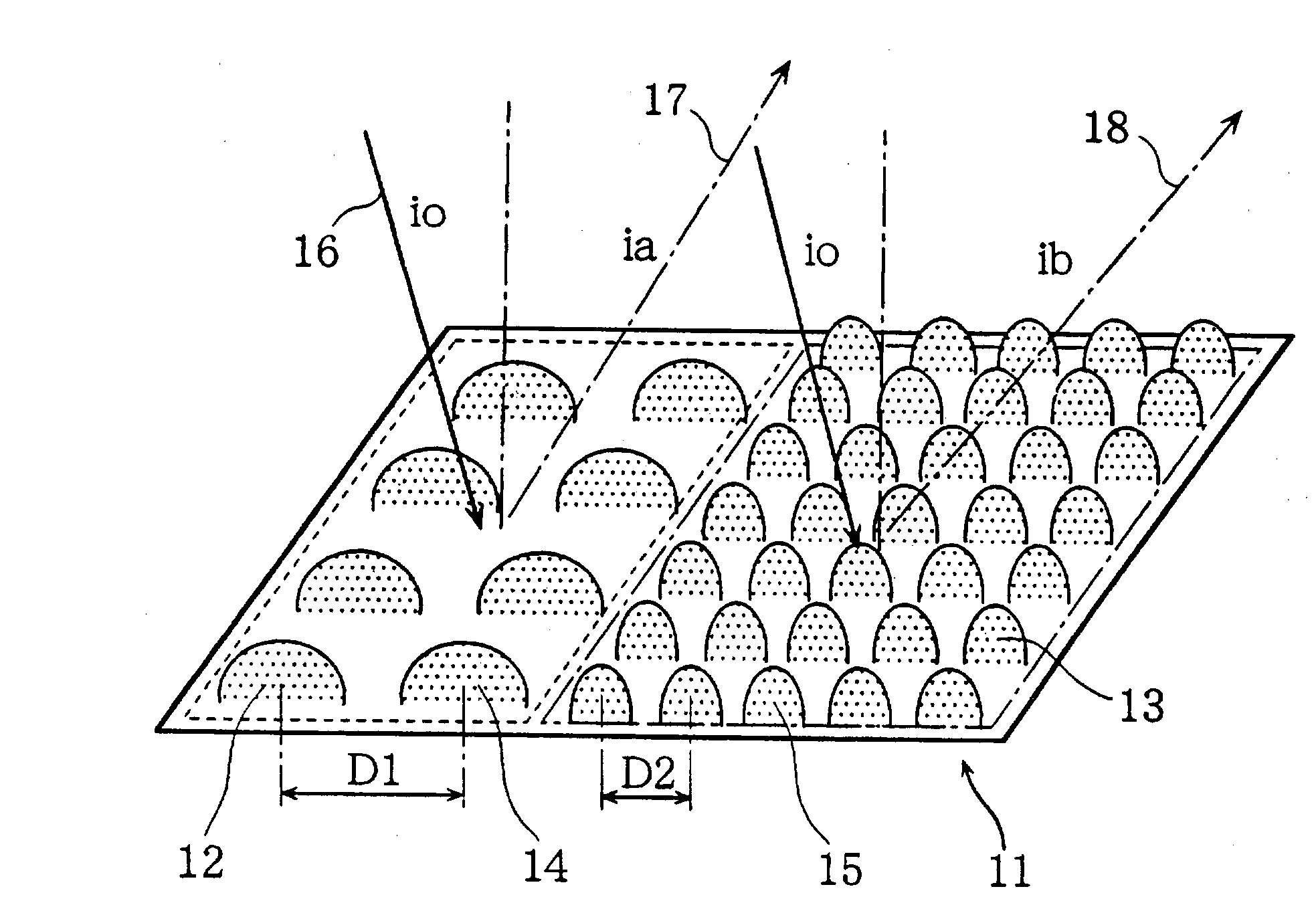
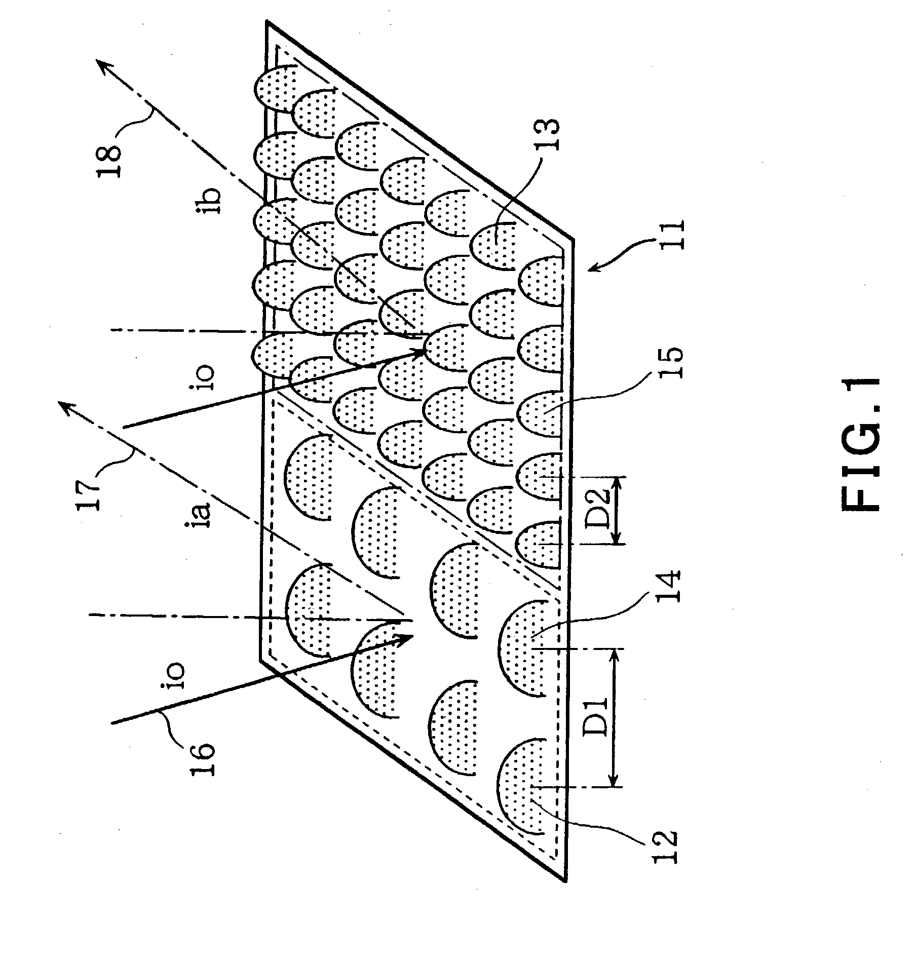
[0155] FIG. 9 is a perspective view of a reflector according to the embodiment 1-3. A reflector 91 that is used in this embodiment comprises convex portions arranged thereon so that recurrency is achieved for each pixel 92. More specifically, the reflector 91 has two different regions, an A region 93 and a B region 94 that are formed thereon with different pitches of the adjacent convex portions. Convex portions 95 formed on the A region 93 are arranged with a pitch D1 of 9 .mu.m between the adjacent convex portions. Convex portions 96 formed on the B region 94 are arranged with a pitch D2 of 7 .mu.m between the adjacent convex portions. The regions A and B are formed for each pixel.

[0156] For the reflector having the above-mentioned configurations, reflection characteristics were assessed, according to similar conditions to those used in the above-mentioned embodiment 1-1, on the reflector having such configurations using the measurement device shown in the a...


PUM


Abstract

In a method for manufacturing a reflector having a plurality of convex portions 4 that are obtained by means of melt deformation of column-shaped bodys 15 formed of a photosensitive resin material, the photosensitive resin material has aspect ratio vs. average tilt angle characteristics in which an average tilt angle theta reaches a maximum value through an incremental change process and then converges to a certain value through a decremental process when an aspect ratio is gradually increased from a value close to zero, provided that the average tilt angle of the convex portion is an angle of elevation from the outer periphery of the bottom surface of the convex portion 4 to an apex of the convex portion and that the aspect ratio is a ratio of the height of said column-shaped body 15 with respect to the width thereof. A set value for the aspect ratio of the column-shaped body 15 that is obtained after the development step is determined to be a larger aspect ratio than a starting point from which convergence to said certain value begins. This configuration provides a reflector having good contrast characteristics and PAPER WHITE APPEARANCE, and a reflective liquid crystal display panel that uses the above-mentioned reflector.

Description

[0001] The present invention relates to a reflector and a reflective liquid crystal display panel as well as to a method for manufacturing them and a manufacturing equipment with which bright and good image display can be provided with lower consumption current by using ambient light.BACKGROUND TECHNIQUE[0002] (First Background Art)[0003] Reflective liquid crystal display devices reflect ambient light from a reflector that is disposed inside the liquid crystal display device to provide a display. No backlight as a light source is required accordingly in contrast to conventional transmissive liquid crystal display devices. Consequently, an increased number of them are mounted on cell phones and portable information terminals, as a display device that can reduce consumption power as compared with transmissive liquid crystal display devices.[0004] Reflective liquid crystal display devices comprises a liquid crystal display mode of, for example, a TN (twisted nematic) type, an STN (suoe...

Claims


Application Information

Patent Timeline
IPC IPC(8): G02B5/02G02B5/08G02F1/1335
CPCG02B5/0226G02B5/0263G02F1/133553G02B5/0284G02B5/08G02B5/0268
Inventor NISHIYAMA, SEIJIWAKITA, NAOHIDEKUBOTA, HIROFUMI
Owner JAPAN DISPLAY CENT INC
Why Eureka
Try Eureka