Method and apparatus for including article identification in an article handling device

a technology of article identification and handling device, which is applied in the direction of de-stacking articles, article separation, instruments, etc., can solve the problems of poor reliability, inability to prevent the dispensing of incorrect products, and their use in tight confines, such as article vending machines, to achieve simple, accurate and reliable construction and operation, and improve the speed and accuracy of the article handling operation. , the effect of preventing any damag

Inactive Publication Date: 2003-08-07
CHIRNOMAS MUNROE
View PDF10 Cites 23 Cited by
  • Summary
  • Abstract
  • Description
  • Claims
  • Application Information

AI Technical Summary

Benefits of technology

0015] It is an even further general object of the present invention to provide new techniques and methods for such mechanisms which improve the speed and accuracy of the article handling operation while still handling the articles to be dispensed in a careful manner so as to prevent any damage thereto.
0016] It is a more specific object of the present invention to provide a method and apparatus for article identification in an article handling apparatus, which not only is relatively simple, accurate and reliable in its construction and operation, but which also has some flexibility in order to help ensure identification and / or recognition of the articles being dispensed.

Problems solved by technology

Such machines generally suffer from numerous disadvantages, such as poor reliability due to mechanical failures, as well known by those skilled in this art.
Although robotic, and specifically suction-type lifting mechanisms are in common use in factory settings, where space limitations are generally relaxed, their use in tight confines, such as an article vending machine, has not gained wide acceptance.
Although the technique disclosed in this patent facilitates rapid and accurate programming of the vending machine during servicing, it can not prevent dispensing of an incorrect product due to erroneous loading of the product into the machine, e.g., such as due to either inadvertently or purposefully loading an incorrect product into an incorrect storage column.
However, it would be possible to relatively easily "trick" or cheat a vending machine of this type by, for example, disabling the bar code scanner at the input end of each storage column, or by holding a false bar code in front of the reader during refilling of that column with a different, maybe erroneous and possibly inferior, product.
By including a bar code reader at the product exit chute of the dispenser, it is significantly more difficult to "trick" or cheat the machine by purposefully restocking the machine with erroneous and possibly inferior product.
However, in this and the above noted JP4123194A2 patent, it would not be uncommon for the fixed position bar code scanner to fail to read and identify the bar codes on the articles as they roll or tumble in a haphazard manner past the bar code scanner at the exit chute.
In the event that the operator of the vending machine tries to "trick" or cheat the machine by tampering with the bar code reader or its activation, a voltage oversurge is provided to the control circuitry of the vending machine, which effectively destroys the control circuitry and renders the machine inoperative.
Improperly stored articles are thus pre-identified, and will not be dispensed.
One disadvantage of these types of systems is that the bar code reader and electrical connections suffer stress due to the many cycles of manipulator arm movement, since the bar code reader is mounted on the manipulator arm.
Furthermore, this kind of positioning for the bar code reader can reduce the reliability of the bar code reading device, and also introduces mechanical and electronic complexity in its construction, due to the necessity of providing electrical connections to a movable bar code reader.
Even furthermore, by positioning the bar code reader on the manipulator arm, restrictions are placed upon the "view" provided to the reader as the manipulator arm is advanced toward the article to be retrieved, leading to an increase of the probability that the article bar code may not be properly read.
This article identification technique suffers from the same problem as before noted patents, namely that the article may pass by the article identification device in a position where it's shape / pattern can not be identified / recognized.

Method used


Image

  • Method and apparatus for including article identification in an article handling device
  • Method and apparatus for including article identification in an article handling device
  • Method and apparatus for including article identification in an article handling device

Examples


Embodiment Construction

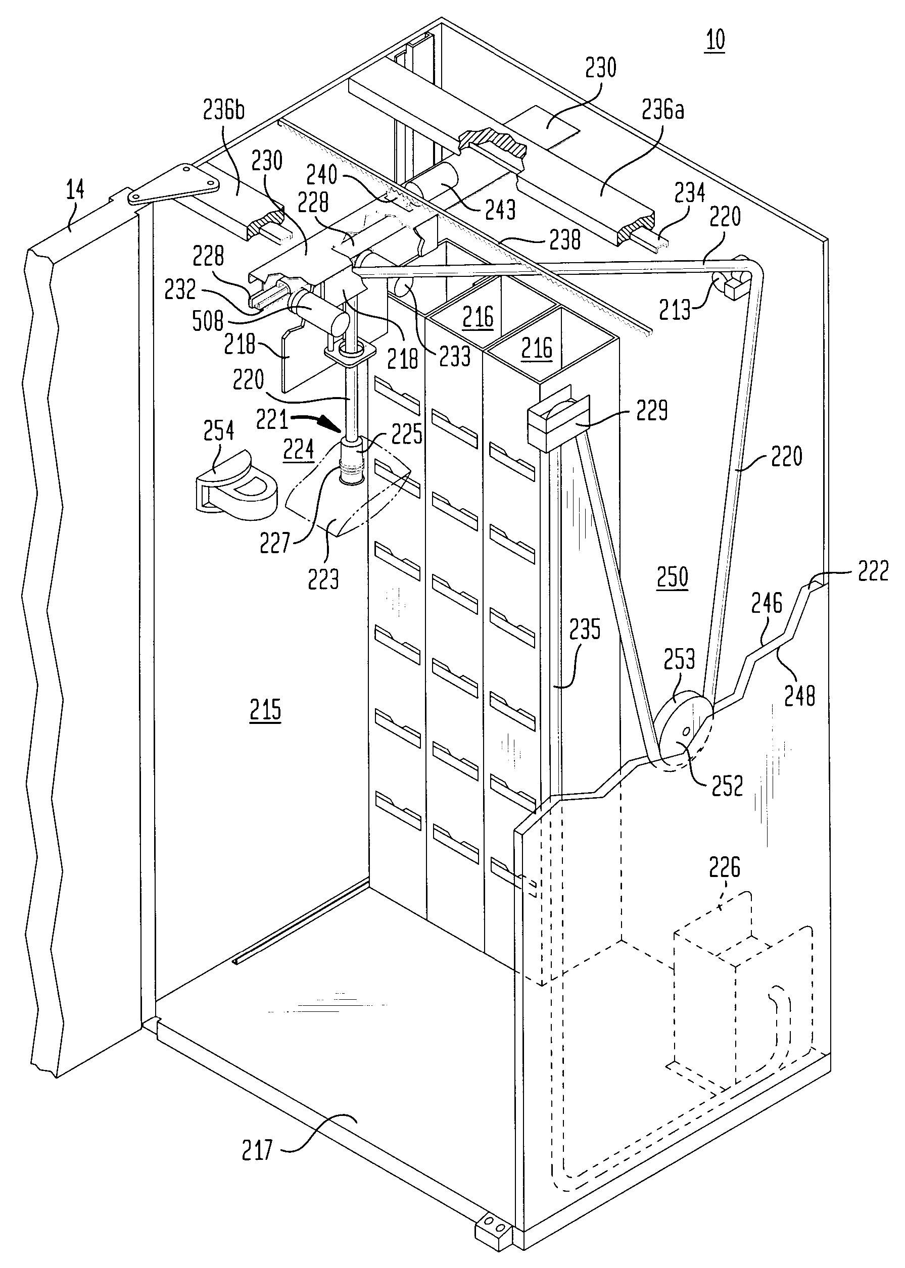
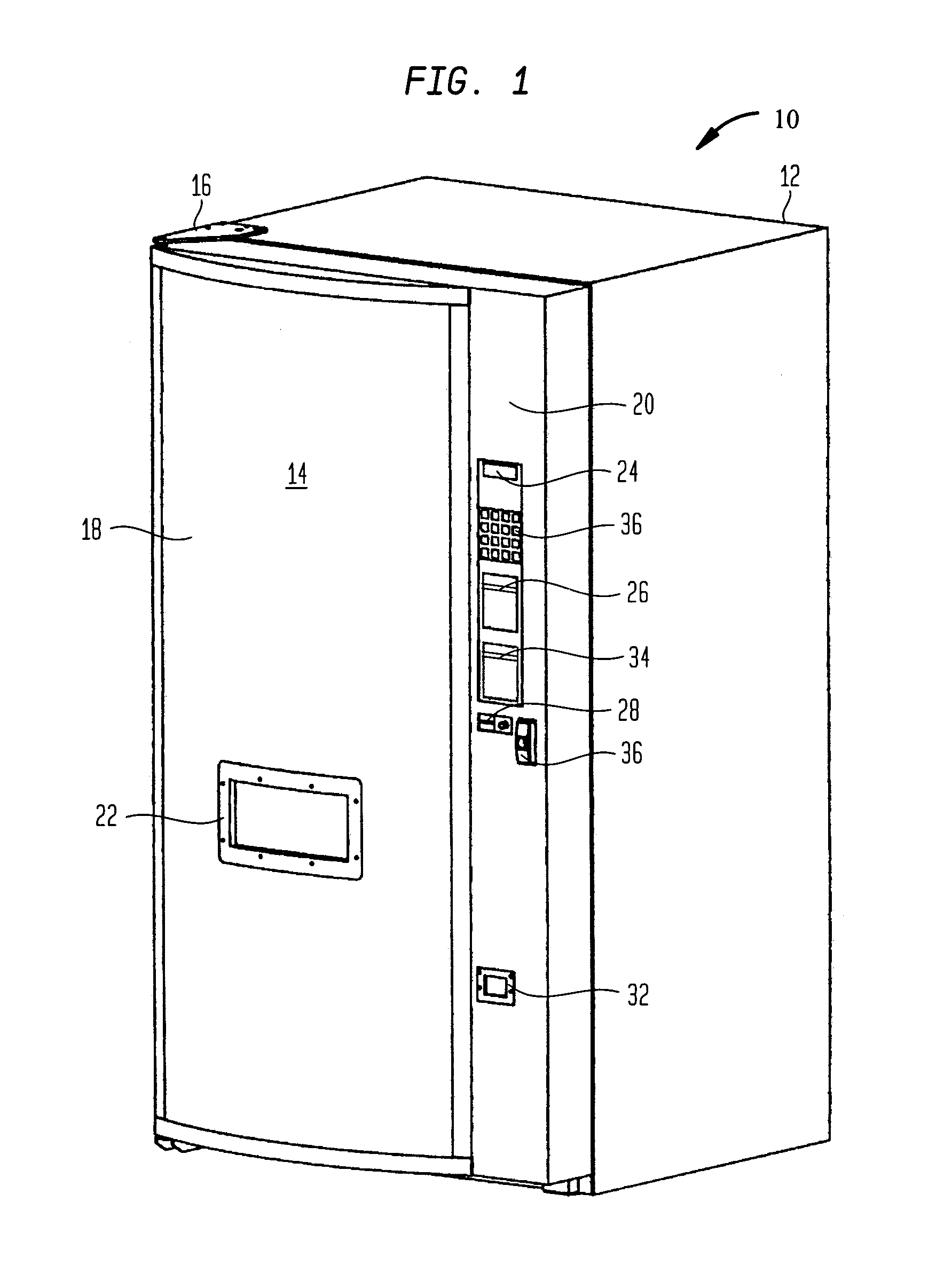
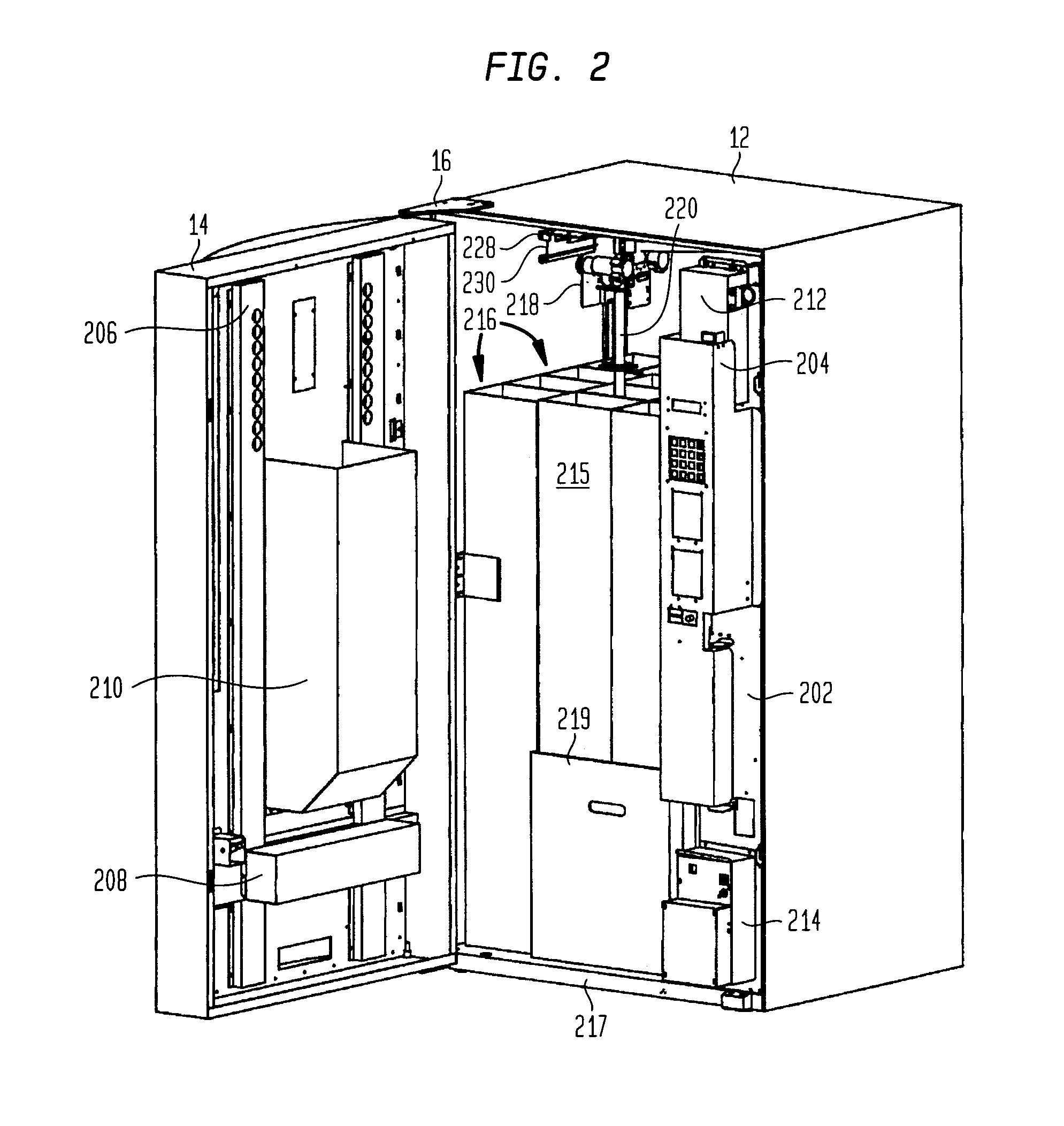
[0021] FIG. 1 illustrates an environment for the invention described herein, in the form of an article dispenser, such as a point-of-sale (POS) dispenser. Although throughout the following description, reference is made to implementation of the invention in a vending machine environment, it is intended that the term "vending machine", and in fact the environment for the present invention, include more general purpose article handling, retrieval and / or dispensing apparatus, as well as POS equipment. Such equipment, if embodied as a portable device may comprise and be about the size of a traditional vending machine or as large as a tractor-pulled trailer, and if embodied as a non-portable device may comprise and be embodied as an automated dispensing room or an area located in a permanent structure, such as in a building (aboveground or underground, and with or without interior walls or an enclosing cabinet). Furthermore, it is intended that the term "articles"or "products" include in...


PUM


Abstract

Abstract of Disclosure The above objects are achieved in an illustrated embodiment of an article dispensing apparatus embodied, for example, as a vending machine, including a controllably positioned suction hose dispenser for retrieving articles from a storage area. In one embodiment, the article dispenser comprises a storage area for storing articles along at least one longitudinal axis in a stack, an article dispensing device for moving the end article from the stack of articles in the storage area along a path to a retrieval area, and an article identification device, mounted within the article retrieving apparatus. The article dispensing device moves the article in a predetermined pattern past the article identification device, so as to provide identification of the article being moved.

Description

Background of Invention[0001] 1. Field of the Invention[0002] The present invention relates generally to improvements in the design and operation of an article handling apparatus used in conjunction with an article identification device, and is particularly useful in the environment of an article handling device as used a vending machine.[0003] 2. Description of the Prior Art[0004] Most prior art article handling mechanisms, more specifically referred to in the description of the present invention as being in the environment of a point-of-sale (POS) article dispenser, rely on a multitude of motors, switches and solenoids for moving various portions of the handling mechanism, and handling of the articles themselves, such as packaged products. Most such machines require one motor, switch and / or solenoid dedicated for each row, column or type of article or package to be handled or dispensed therefrom. Such machines generally suffer from numerous disadvantages, such as poor reliability ...

Claims


Application Information

Patent Timeline
Patent Type & Authority Applications(United States)
IPC IPC(8): G07F11/02G07F11/16
CPCG07F11/02G07F11/165G07F11/16
Inventor CHIRNOMAS , MUNROE
Owner CHIRNOMAS MUNROE
Why Eureka
Try Eureka