Four-cycle overhead valve engine

Inactive Publication Date: 2003-08-14
KAWASAKI MOTORS LTD
View PDF0 Cites 6 Cited by
  • Summary
  • Abstract
  • Description
  • Claims
  • Application Information

AI Technical Summary

Problems solved by technology

In this type of the known four-cycle overhead valve engine, the engine cylinder block tends to be bulky in size, having a lateral wall protrusion for accommodating the breather passage at such another portion of the cylinder wall opposite to the portion where the push rods are accommodated.
In this second mentioned four-cycle overhead v

Method used


Image

  • Four-cycle overhead valve engine
  • Four-cycle overhead valve engine
  • Four-cycle overhead valve engine

Examples


Example

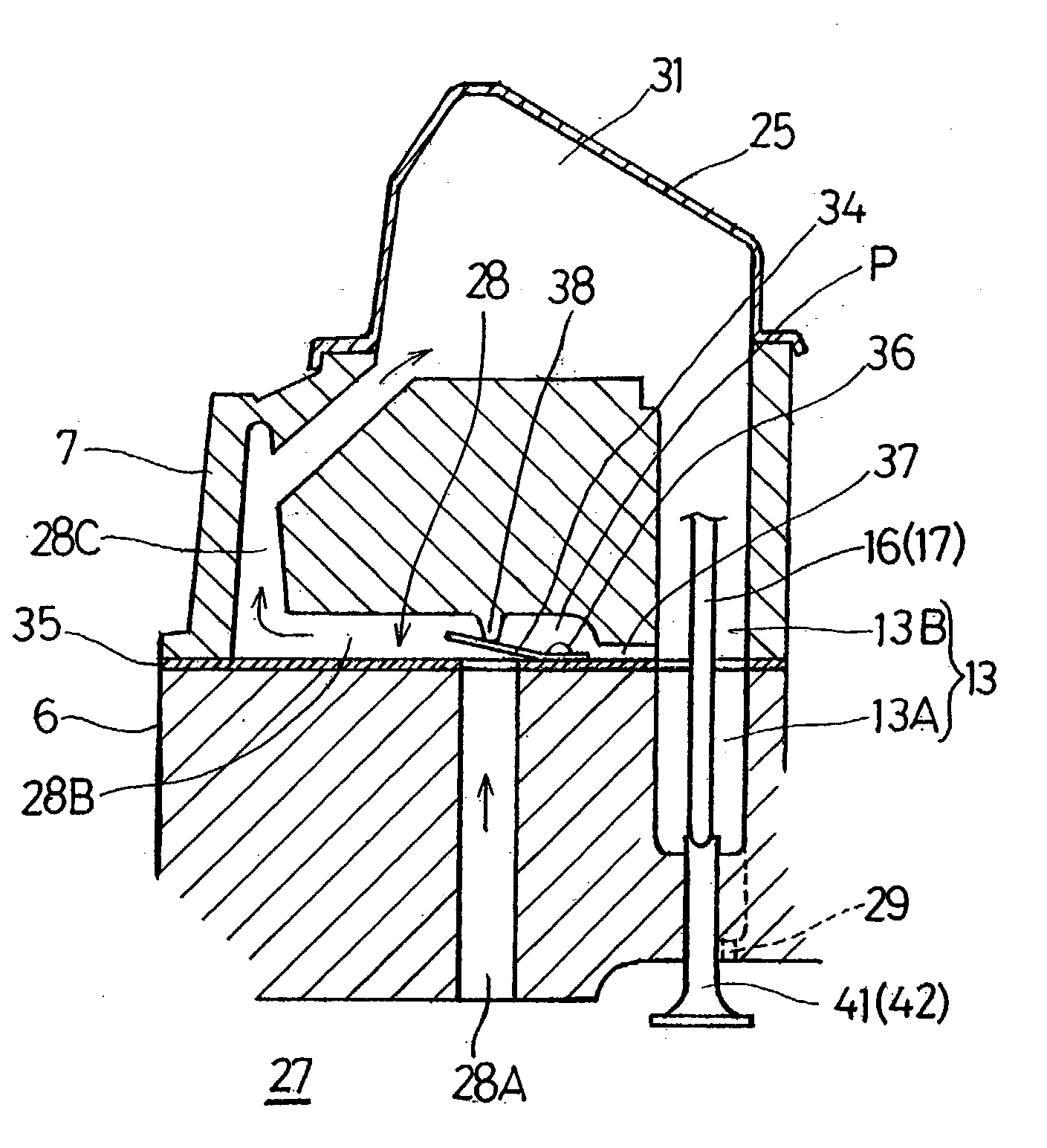
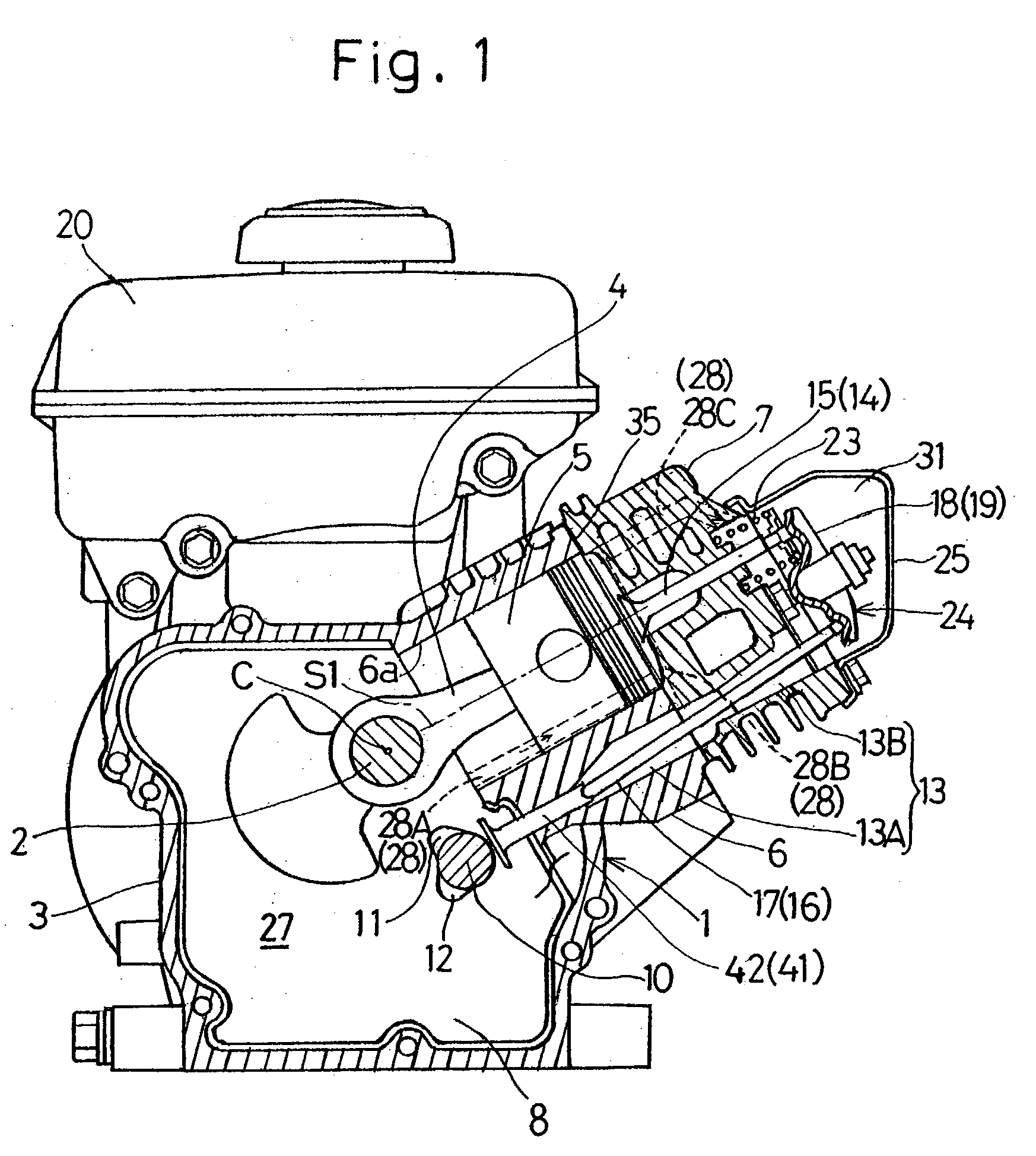
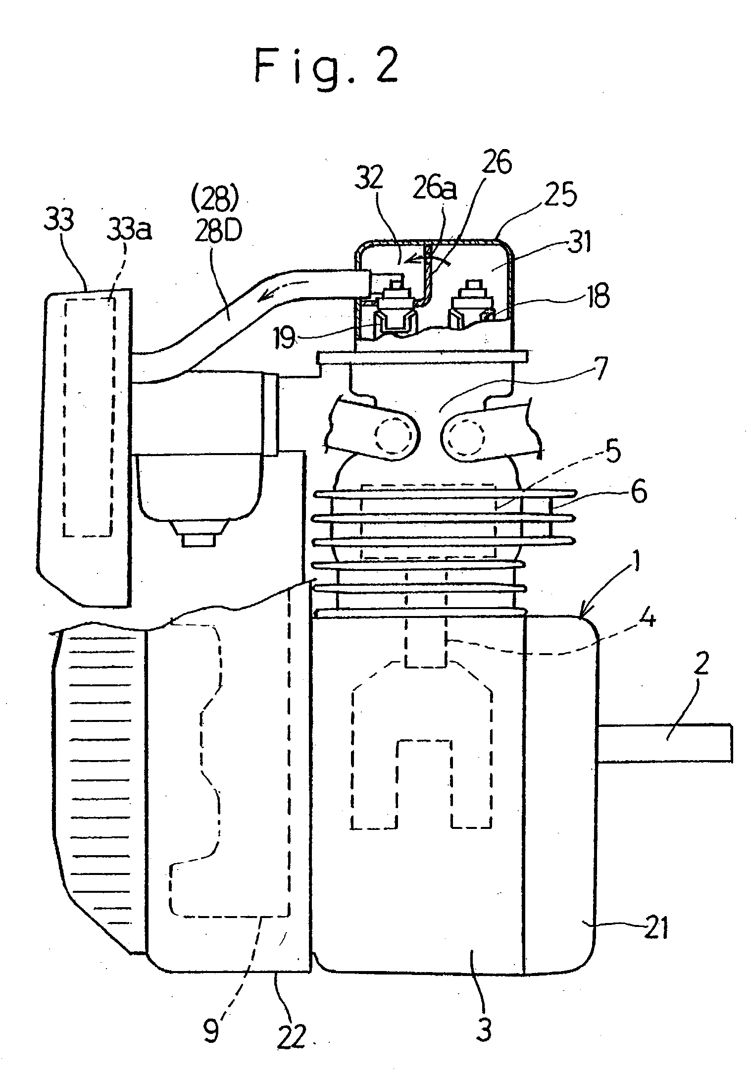
[0026] With reference to the accompanying drawings, a preferred embodiment of the present invention will be described in detail. Specifically, FIGS. 1 and 2 show a four-cycle overhead valve engine embodying the present invention in a front sectional view and a fragmentary side view, respectively.

[0027] As shown in FIG. 1, the four-cycle overhead valve engine includes a engine body 1 provided with a crankcase 3 for rotatably supporting a horizontally lying crankshaft 2, a cylinder block 6 formed integrally with the crankcase 3, a piston 5 drivingly connected with the crankshaft 2 through a connecting rod 4 and accommodated within a cylinder bore 6a defined in the cylinder block 6 for sliding movement within the cylinder bore 6a, and a cylinder head 7 separate from the cylinder block 6 and mounted atop the cylinder block 6. The cylinder bore 6a of the cylinder block 6 has a longitudinal axis S1 and is disposed with its longitudinal axis S1 inclined relative to a horizontal direction a...


PUM


Abstract

To provide a four-cycle overhead valve engine wherein the breather passage is defined to avoid an undesirable increase in size of the engine as a whole and also to avoid increase in length of the breather passage, a four-cycle overhead valve engine is provided which includes a cylinder block (6), and push rods (16 and 17) for driving intake and exhaust valves (14 and 15), respectively, that are mounted above the cylinder block (6). A breather passage (28) connecting a crank chamber (27) and a rocker arm chamber (31) with each other is made up of a first passage portion (28A) defined in the wall of the cylinder block (6) at a location adjacent a flywheel (9) and the push rods (16 and 17), and a second passage portion (28B) extending from one side adjacent the push rods (16 and 17) in a direction away from the push rods (16 and 17). A check valve (34) for the breather passage (28) is disposed at a junction between the first and second passage portions (28A and 28B).

Description

[0001] 1. (Field of the Invention)[0002] The present invention relates to a four-cycle overhead valve engine including intake and exhaust valves mounted atop a cylinder block and push rods arranged in a lateral portion of the cylinder block for driving the intake and exhaust valves.[0003] 2. (Description of the Prior Art)[0004] In the four-cycle overhead valve engine now in use, push rods for driving respective intake and exhaust valves mounted above an engine cylinder block are disposed in a portion of the wall of the engine cylinder block laterally of a cylinder bore in which a piston reciprocates and a breather passage for communicating a crank chamber and a rocker arm chamber together is disposed in another portion of the wall of the engine cylinder block laterally of the cylinder bore remote from the push rods, for example, spaced 180.degree. from the push rods with respect to a cylinder axis of the cylinder bore.[0005] In this type of the known four-cycle overhead valve engine...

Claims


Application Information

Patent Timeline
IPC IPC(8): F01L1/14F01M13/00F02B75/02F02F1/00F02M25/06
CPCF01M13/0011F01M2013/0016Y02T10/121F02M25/06F02B2075/027Y02T10/12
Inventor NAKAMIZO, KEIICHIAKASE, SHINYA
Owner KAWASAKI MOTORS LTD
Why Eureka
Try Eureka