Low latency video decoder with high-quality, variable scaling and minimal frame buffer memory

a video decoder and low latency technology, applied in the field of low latency video decoders, can solve the problems of increasing the time gap between the end of the picture display and the pts synchronization point, correspondingly significant amount of decoding time lost, and complicating synchronization

Active Publication Date: 2003-08-21
TWITTER INC
View PDF15 Cites 45 Cited by
  • Summary
  • Abstract
  • Description
  • Claims
  • Application Information

AI Technical Summary

Problems solved by technology

As can be appreciated by those skilled in the art, if the bottom of any arbitrarily scaled and located image is significantly above the bottom of the display frame, a correspondingly significant amount of decoding time is lost since the entire image must be decoded and processing for scaling and positioning performed well before the end of the display frame or field (where the PTS synchronization point is typically located) is reached.
Further, as the picture position rises on the screen, the time gap between the end of the picture display and the PTS synchronization point, also referred to as the frame switch point, increases as does the error in the calculation for monitoring PTS synchronization.
Longer decode latency is a possible solution although it may complicate synchronization and, more importantly, carries substantial hardware costs that are commercially unacceptable to provide the amount of memory required to store the decoded image (and audio) data for the increased period.
If a spill buffer is not provided, this period, subsequent to the PTS timing, would also be lost for decoding purposes since no memory locations would be available to receive decoded data in the frame buffer.
Again, provision of such amounts of memory as is required by spill buffers in STBs is prohibitive and will be so well into the future.
Additionally, as images are scaled to smaller sizes the image quality tends to degrade since the frame buffers are constructed with a finite number of taps to subsample the image data.
The number of taps is not increased and cannot be effectively increased as the picture is scaled.
Variation of the number of effective taps with picture size that is desirably continuously variable is also prohibitively complicated for inclusion in STBs.
Due to the memory requirements alluded to above and the difficulty of increasing speed of decoding, at some point, achieving display of small and high-positioned images requires an adjustment between decode and display latency.
Performing scaling in the decoding path reduces the amount of required data storage capacity in the frame buffer to the point that a spill buffer may not be used and its size thus limited as may be dictated by economic constraints.
However, this function is substantially less than the full desired flexibility of continuous and arbitrarily variable image scaling.
In summary, decoding of B images is the most difficult among the types of image a STB may be required to decode because they are the most compressed and require a greater number of references to previous and future decoded images in the decoding process.
Decoding of B images also presents the most demanding requirements for scheduling buffering and output of the decoded image data.

Method used


Image

  • Low latency video decoder with high-quality, variable scaling and minimal frame buffer memory
  • Low latency video decoder with high-quality, variable scaling and minimal frame buffer memory
  • Low latency video decoder with high-quality, variable scaling and minimal frame buffer memory

Examples


Embodiment Construction

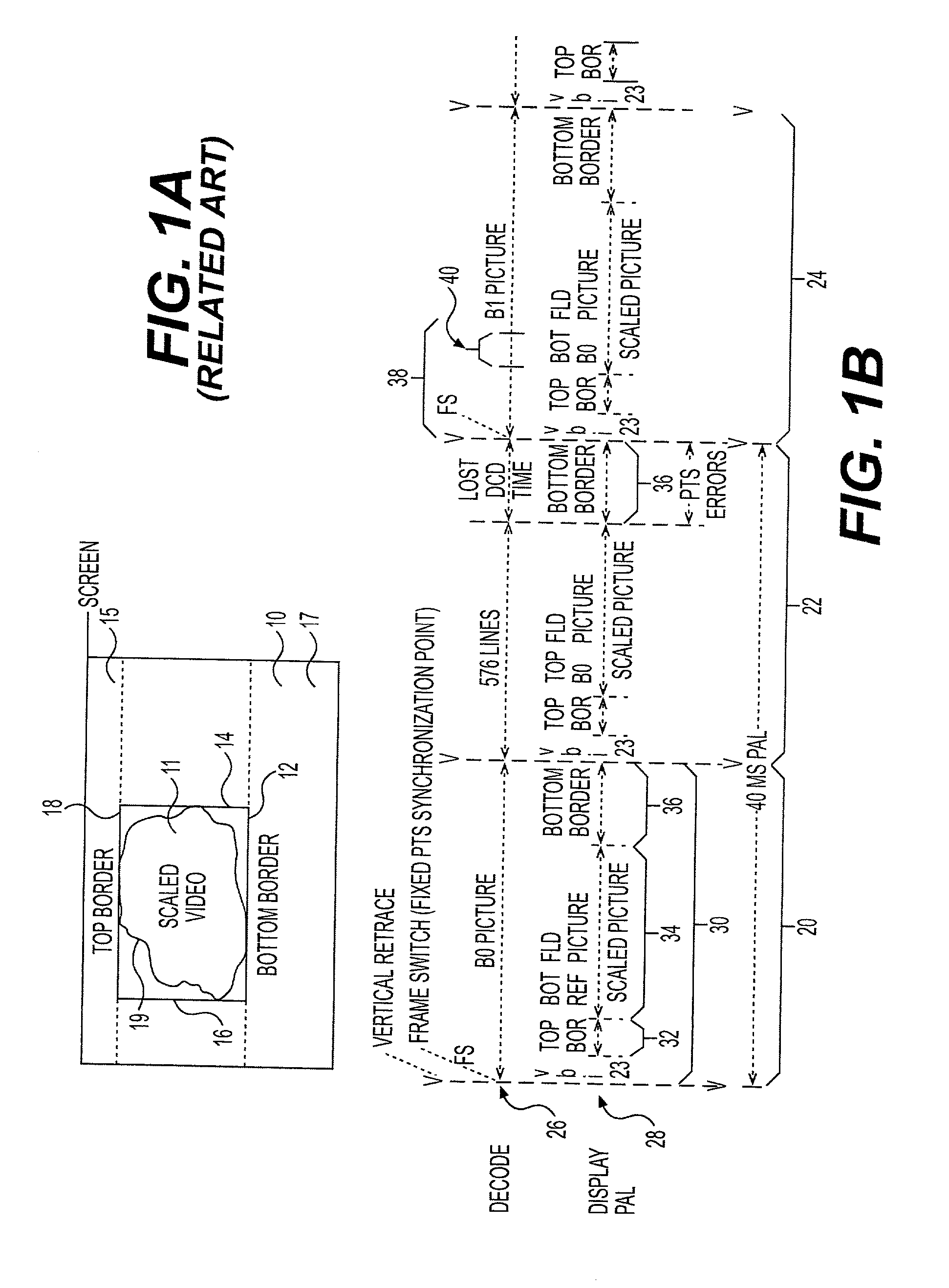
[0033] Referring now to the drawings, and more particularly to FIGS. 1A and 1B, there is shown a depiction of a motion video image arbitrarily scaled and positioned on a display area of a display screen and a timing diagram corresponding to the above-described scenario that will be useful in understanding the problem addressed by the invention, respectively. Referring to FIG. 1A, particularly for definition of terminology used herein, a rectangular display area 10 is provided which corresponds to the raster size of the display but may or may not correspond to the dimensions of the hardware display screen. However, it will often be the case that the screen area and the display area 10 will be congruent and, for simplicity, the terms screen and display area may be used interchangeably. Within this display area 10 a rectangular scaled motion video area 11 having boundaries 12, 14, 16 and 18, defines a top border area 15 and a bottom border area 17.

[0034] It should be understood that th...


PUM


Abstract

Loss of decoding time prior to the vertical synchronization signal when motion video is arbitrarily scaled and positioned by placing the frame switch point at the completion of frame decoding and synchronizing the bottom border of the scaled image therewith while maintaining low latency of decoded data. High latency operation is provided only when necessitated by minimal spill buffer capacity and in combination with fractional image size reduction in the decoding path in order to maintain image resolution without requiring additional memory.

Description

[0001] 1. Field of the Invention[0002] The present invention generally relates to decoding of digital video image information and, more particularly, to decoding of digital motion video signals with high quality and arbitrary scaling and positioning while achieving low latency and minimal memory capacity requirements.[0003] 2. Description of the Prior Art[0004] Transmission of data in digital form is generally favored over transmission in analog form at the present time in view of the inherent degree of noise immunity and potential for facilitating error correction and data compression. These qualities are particularly desirable in regard to image data where small artifacts caused by noise or transmission errors are particularly evident to the eye. However, the volume of data that may be necessary to express a full range of color and intensity in an image at high resolution is particularly large and data compression is particularly important for acceptable performance of systems for...

Claims


Application Information

Patent Timeline
Patent Type & Authority Applications(United States)
IPC IPC(8): H04N5/00H04N7/26H04N7/46H04N7/50H04N7/62
CPCH04N21/4307H04N21/4312H04N21/44004H04N21/440263H04N19/577H04N19/174H04N19/17H04N19/423H04N19/426H04N19/61H04N21/43072
Inventor CAMPISANO, FRANCESCO A.CHENEY, DENNIS P.HRUSECKY, DAVID A.
Owner TWITTER INC
Why Eureka
Try Eureka