

Decimal set point clock generator and application of this clock generator to UART circuit
a clock generator and decimal set point technology, applied in pulse generators, electric digital data processing, instruments, etc., can solve the problems of large volume of voltage-controlled oscillators, inability to meet the requirements of synchronization, so as to achieve fine steps and reduce synchronization errors
- Summary
- Abstract
- Description
- Claims
- Application Information
AI Technical Summary
Benefits of technology
Problems solved by technology
Method used
Image

Examples
example a
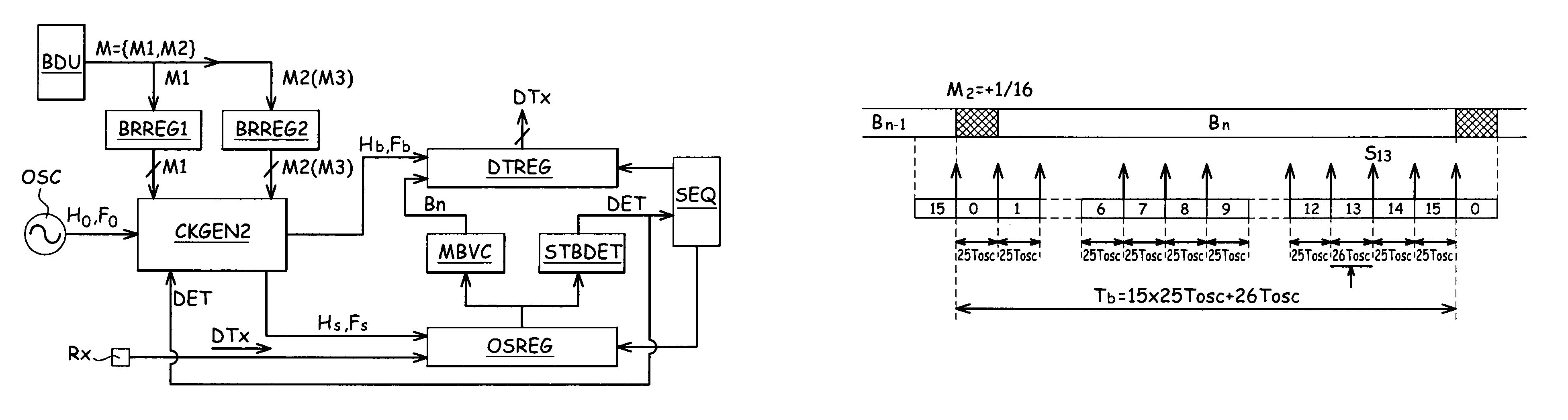
, FIG. 7
[0200]This example corresponds to the case where M2=+ 1 / 16 (i.e., 0.06). It can be seen that the period of the fourteenth pulse S13 is equal to 26*To while the fifteen other pulses have a period equal to 25*To. In this case:
[0201]M=M1+M2=25.06
[0202]Tb=15*25To+26*To
[0203]Tb=(15*25+26) To
[0204]Tb=401 To
[0205]Fb=Fo / 401
[0206]Tsav=401 / 16 To
[0207]Tsav=25.0625 To
[0208]Fsav=Fo / 25.0625
example b
, FIG. 8
[0209]This example corresponds to the case where M2=+ 2 / 16 (i.e., 0.12). It can be seen that the period of the first pulse SO and of the fourteenth pulse S13 is equal to 26*To (i.e., (M1+1)*To) while the fourteen other pulses have a period equal to 25*To. In this case:
[0210]M=M1+M2=25.12
[0211]Tb=14*25To+2*26*To
[0212]Tb=(14*25+2*26) To
[0213]Tb=402To
[0214]Fb=Fo / 402
[0215]Tsav=402 / 16 To
[0216]Tsav=25.125 To
[0217]Fsav=Fo / 25.125
example c
, FIG. 9
[0218]This example corresponds to the case where M2=− 1 / 16 (i.e., −0.06). The period of the first pulse S0 is equal to 24*To (i.e., (M1−1)*To) while the fifteen other pulses have a period equal to 25*To. In this case:[0219]M=M1+M2=24.94[0220]Tb=15*25To+24*To[0221]Tb=T0(15*25+24) To[0222]Tb=399 To[0223]Fb=Fo / 399[0224]Tsav=399 / 16 To[0225]Tsav=24.9375[0226]Fsav=Fo / 24.9375
[0227]In the examples above, Fsav is the average frequency of the signal Hs over a duration of 16 periods.
[0228]It will be understood by those skilled in the art that the present invention is susceptible of various embodiments and applications.
[0229]In particular, the modulation of the period Ts of the pulses of the oversampling clock signal Hs may be done, as described above, exclusively by positive values (Ts=(M1+1)*To) or exclusively by negative values (Ts=(M1−1)*To).
[0230]The present invention is further susceptible of various applications in fields other than asynchronous data transmissions, and generally ...
PUM
 Abstract
Description
Claims
Application Information