Servo controller

a servo controller and controller technology, applied in the direction of electric controllers, program control, electric programme control, etc., can solve the problems of large positional deviation, large synchronization error, and inability to obtain learning effects, so as to reduce synchronization error, reduce synchronization error, and easily adjust the value

Inactive Publication Date: 2008-09-11
FANUC LTD
View PDF12 Cites 44 Cited by
  • Summary
  • Abstract
  • Description
  • Claims
  • Application Information

AI Technical Summary

Benefits of technology

[0010]It is an object of the present invention to provide a servo controller that can reduce, when the first control is performed, the synchronization error which may arise between a master driving source and a slave driving source.
[0011]In order to attain the above object, in accordance with an aspect of the present invention, there is provided a servo controller that controls a master driving source for driving a driving shaft in synchronism with a slave driving source for driving a driven shaft in a prescribed timing relative to the driving shaft, comprising a position control section that performs position control based on a positional deviation representing a difference between a position command value given to said slave driving source and a feedback value detected by said slave driving source, an operational section that calculates a synchronization error as a difference between a positional deviation on a side of a master driving source and a positional deviation on a side of a slave driving source, and a correction data calculating section that calculates the first correction data for correcting said positional deviation on the side of the slave driving source based on said position command value given to said slave driving source so as to reduce the synchronization error.
[0012]In accordance with the construction as described above, since the correction data calculating section calculates the first correction data for correcting the positional deviation on the side of the slave driving source based on the position command value and the first correction data are added to the positional deviation on the side of the slave driving source, the control can be performed such that the synchronization error between the master driving source and the slave driving source may be reduced. Thus, when the first control is performed and the effect of learning cannot be obtained, highly precise and efficient processing can be performed, and reliability of the product quality can be improved. It is also possible to flexibly accommodate to change of the control method.

Problems solved by technology

However, when the moment of inertia of the rotational shaft increases with increasing rigidity of the rotational shaft, or when the rotational shaft is rotated in high speed, the servo characteristics of the rotational shaft may become lower than that of the feed shaft, and this may give rise to a large positional deviation at the time of acceleration or deceleration of the rotational shaft.
Although such a synchronization error can be gradually converged to a small value by learning control, the effect of learning control can be achieved only after the position command is repeated many times. Therefore, there was a problem that the effect of learning could not be obtained in the first time control, resulting in a large synchronization error.

Method used


Image

  • Servo controller
  • Servo controller
  • Servo controller

Examples


first embodiment

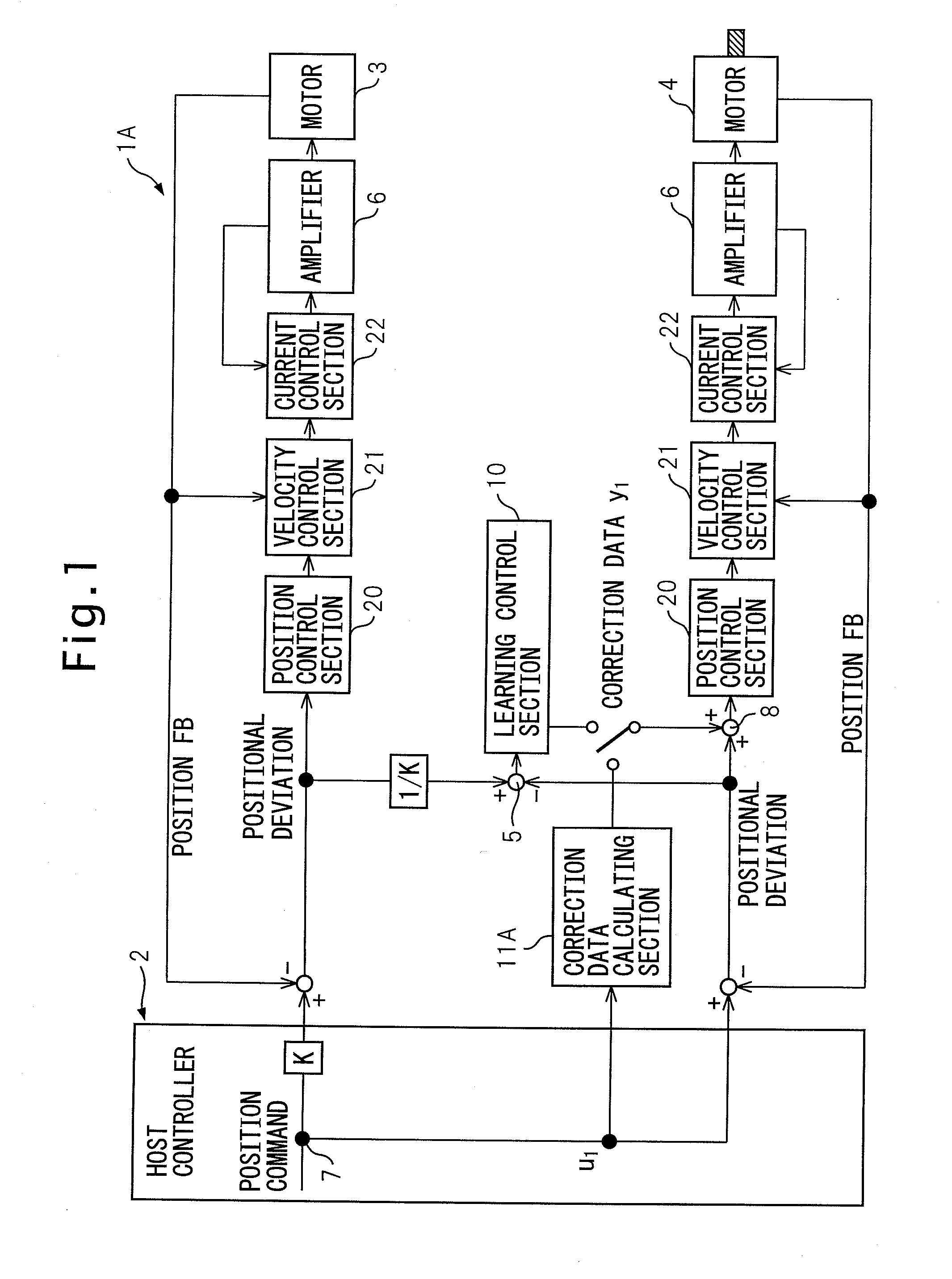
[0036]The present invention will be described in detail with reference to drawings showing specific examples of the preferred embodiments thereof. FIG. 1 is a block diagram of a servo controller according to the present invention. A servo controller 1A according to this embodiment is connected via a shared memory (not shown) to a host controller 2. A movement command value from the host controller 2 is outputted to the servo controller, and is a command value for synchronously controlling a spindle motor (master servo motor) 3 which drives a main shaft (driving shaft) of a machine tool and a feed servo motor (slave servo motor) 4 which drives a driven shaft in linear movement. A positional deviation is obtained by subtracting, from a position command value, a position feedback value obtained from a position detector (not shown) mounted on the servo motors 3, 4 for detecting the position of the servo motors 3, 4. On the slave side, a correction data (second correction data) from a le...

second embodiment

[0055]Next, a servo controller according to the present invention will be described with reference to FIGS. 4 to 7. Effect of learning cannot be obtained in the first time control because there is no reference data (data of synchronization error) available in the learning control section 16. The correction data calculating section 11B of the present embodiment provides the reference data to the initial value setting division 18 of the learning control section 12 so that the servo controller 1B according to the present embodiment can reduce the synchronization error, when the first control is performed.

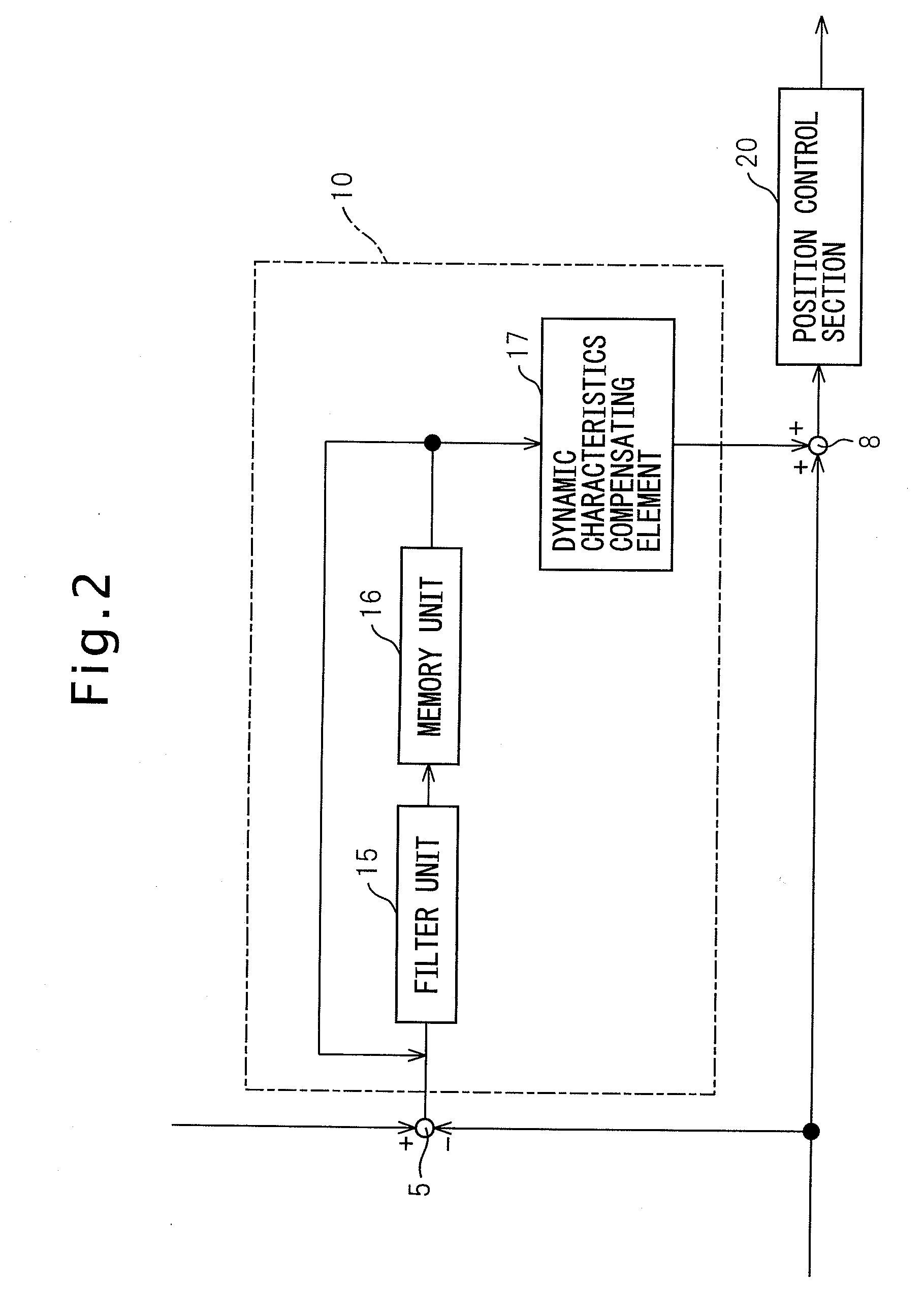
[0056]As shown in FIG. 5, the learning control section 12 comprises a filter unit 15 for limiting the bandwidth, a memory unit 16 for storing the correction data, a dynamic characteristics compensating element 17 for compensating the phase delay or the gain drop of the feed servo motor 4 to be controlled, and in addition, an initial value setting division 18 for setting the data (synch...

fourth embodiment

[0065]Next, a servo controller according to the present invention will be described with reference to FIGS. 10-11. A servo controller 1D of this embodiment can estimate the synchronization error without delay. A correction data calculating section 11E comprises, in addition to a compensator 20 and an adaptive arithmetic logic unit 21, an adjustor 26 and an ON / OFF switch 24. The correction data calculating section 11E, after performing adaptive control to converge the estimated error, turns the switch 24 ON to stop the operation of the adaptive arithmetic logic unit 21 and performs control with fixed filter coefficients. If the synchronization error contains delay, the synchronization error can be reduced by estimating the estimated positional deviation from the position command value.

[0066]The present invention is not limited to the above-described embodiments, but can be implemented in various modifications. For example, also in the third and the fourth embodiments, the servo contr...


PUM


Abstract

A servo controller for synchronously controlling a master driving source for driving a driving shaft and a slave driving source for driving a driven shaft, having a position control section that performs a position control based on a positional deviation which is a difference between a position command value given to the slave driving source and a feedback value detected from the slave driving source, an operational section that calculates a synchronization error which is a difference of the positional deviation between the master driving source and the slave driving source, and a correction data calculating section that calculates first correction data for correcting the positional deviation of the slave driving source.

Description

CROSS REFERENCE TO RELATED APPLICATIONS[0001]The present application claims the benefit of priority based on Japanese Patent Application No. 2007-058442 filed on Mar. 8, 2007, disclosure of which is incorporated herein in its entirety by reference.BACKGROUND OF THE INVENTION[0002]1. Field of the Invention[0003]The present invention relates to a servo controller which is applied to a machine tool for machining a work piece, or a robot, a press machine, an injection molding machine, and the like, that controls a master driving source and a slave driving source in synchronism with each other for performing repeatedly the same machine processing operation such as thread cutting or tapping operation on a work piece.[0004]2. Description of the Related Art[0005]Generally, when an external thread is cut on an outer circumferential surface of a work piece, the thread cutting operation is performed by providing a thread cutting tool with a predetermined cutting depth and moving the thread cut...

Claims


Application Information

Patent Timeline
Patent Type & Authority Applications(United States)
IPC IPC(8): G05B19/18G05D23/275G05B11/32G05B19/10G05B1/06
CPCG05B19/19G05B2219/42141G05B2219/42186G05B2219/50234G05B2219/45214G05B2219/45216G05B2219/42249
Inventor MAEDA, KAZUOMISONODA, NAOTOTOYOZAWA, YUKIO
Owner FANUC LTD
Why Eureka
Try Eureka