Fuel hose, fuel hose connection method, and fuel hose connection structure

a technology of fuel hoses and hoses, which is applied in the direction of hose connections, sleeve/socket joints, mechanical devices, etc., can solve the problems of increasing the cost of fuel hoses, difficult pipe inserting, and low fuel permeability, and achieves superior fuel sealing properties and reduces insertion force. , the effect of low fuel permeability

Inactive Publication Date: 2003-08-28
SUMITOMO RIKO CO LTD
View PDF3 Cites 8 Cited by
  • Summary
  • Abstract
  • Description
  • Claims
  • Application Information

AI Technical Summary

Benefits of technology

0004] The present invention provides a fuel hose having low fuel permeability when connecting to pipes and superior fuel sealing properties. The fuel hose of the present invention also reduces the insertion force required to insert the pipe and does not require special increases in cost. Additionally, the present invention provides a method and an apparatus for connecting the fuel hose. Furthermore, the present invention effectively handles the unavoidable degradation in fuel permeability and sealing properties due to aging of the material in the fuel hose connection structure.

Problems solved by technology

However, since a fixed amount of fuel seeps into the contact section between the inner layer and the pipe, this conventional hose does not provide low fuel permeability, which is required due to stricter regulations on fuel permeability and the like.
However, since the pipe is inserted into the hard fluorocarbon resin tube 2 having the sealing rubber 3 on the inner perimeter surface, the pipe is difficult to insert since the required insertion force is very high.
Also, the sealing rubber 3 is made of a rubber material having low fuel permeability which is expensive, thereby increasing the cost of the fuel hose.
Furthermore, the vulcanized adhesion process used for preventing misalignment of the sealing rubber 3 when the pipe is inserted also increases the cost of the fuel hose.

Method used


Image

  • Fuel hose, fuel hose connection method, and fuel hose connection structure
  • Fuel hose, fuel hose connection method, and fuel hose connection structure
  • Fuel hose, fuel hose connection method, and fuel hose connection structure

Examples


Embodiment Construction

(FIG. 3)

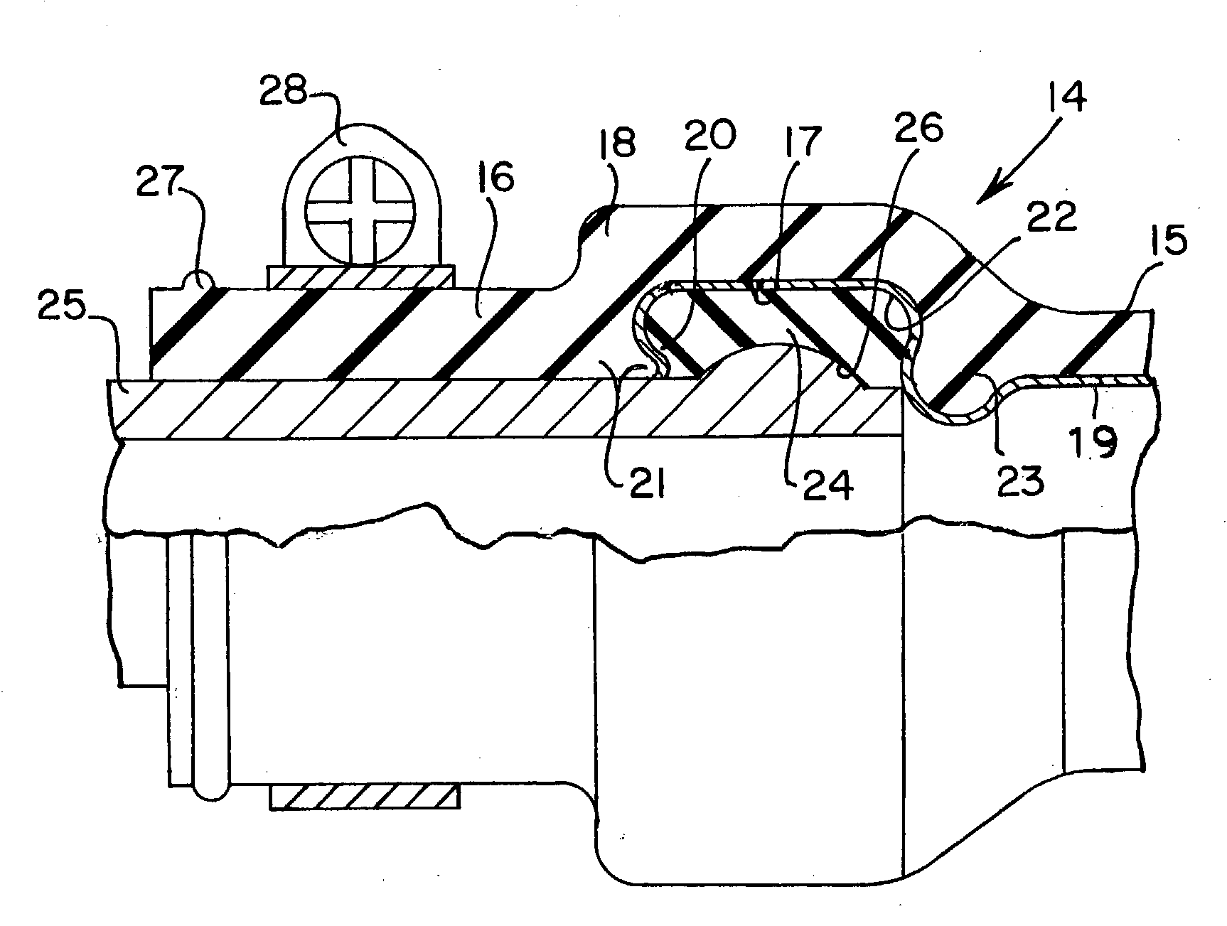
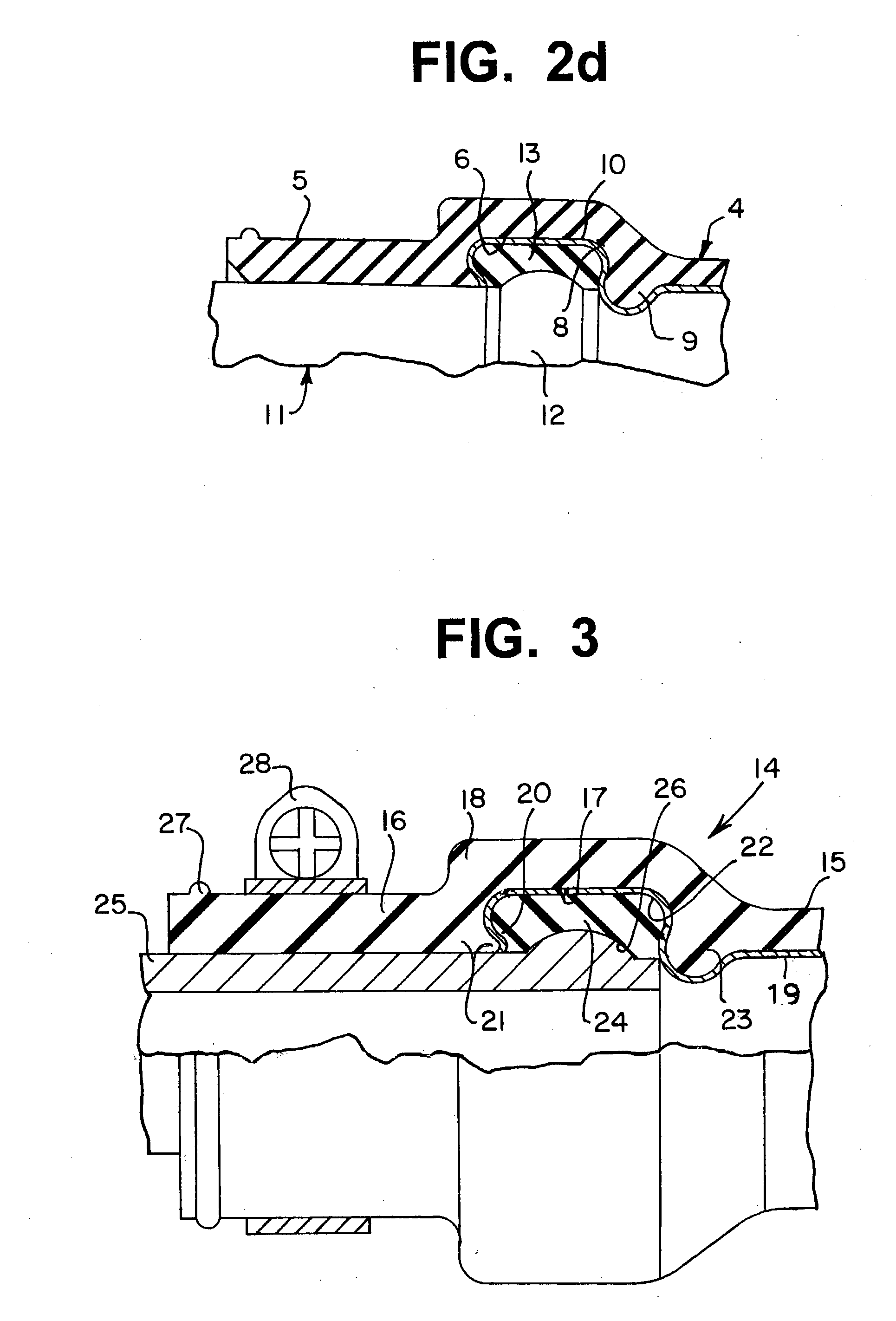
[0103] FIG. 3 shows a fuel hose connection structure according to an embodiment of the present invention. The scope of the present invention is not restricted in any way by this embodiment.

[0104] A fuel hose 14 shown in FIG. 3 has a straight opposing member insertion section 16 formed at the end of a metal or resin hose tube 15. Along an axis of the fuel hose 14 (i.e., the hose axis), there is an end side (to the left in FIG. 3) and a center side (to the right in FIG. 3) of the fuel hose. A ring-shaped groove 17 is formed on the inner perimeter surface of the opposing member insertion section 16 toward the center side of the fuel hose along the hose axis. A thick section 18 extends outward in the radial direction from the outer perimeter section of the hose tube 15 to reinforce the thickness of the opposing member insertion section 16. Also, a thin resin layer 19 having a thickness of 200 microns is applied over the inner perimeter surface of the ring-shaped groove 17 and ov...


PUM


Abstract

A straight opposing member insertion section located at the end of a hose tube and has a ring-shaped groove for inserting a sealing ring. The opposing member insertion section has a ring-shaped tongue piece and/or a ring-shaped ring supporting section. Tongue-piece has a sloped surface and an overhang positioned over the ring-shaped groove. Ring supporting section is an indentation on the ring-shaped groove that protrudes away from the end of the hose tube. A sealing ring is tightly inserted into the ring-shaped groove. A ring-shaped engagement projection on the end of the tube-shaped opposing member is pushed into the opposing member insertion section until the engagement projection abuts the sealing ring. Sealing ring and the section of the tube wall with the ring-shaped groove can be constructed to handle seal deterioration. The resulting fuel hose connection structure has superior fuel sealing properties, fuel impermeability and can be contructed simplely and inexpensively.

Description

[0001] The present invention relates to a method and an apparatus More specifically, the present invention relates to a fuel hose connection method that involves using a ring-shaped sealing member, a hard, pipe-shaped opposing member, and a fuel hose. The opposing member can be a pipe made of metal or resin. The fuel hose has an opposing member insertion section for ensuring a fluid-tight connection between the opposing member and the fuel hose. The present invention also relates to a fuel hose connection structure based on the fuel hose connection method.[0002] U.S. Pat. No. 5,664,608 (EP 0591831 A2) discloses a conventional, multi-layer hose with an outer layer made of rubber. Except for a pipe insertion section, the inner perimeter surface of the hose has a thin inner layer made of a hard metal or resin material having low fuel permeability. The publication states that fuel seepage to the outside is adequately prevented since the section of the inner perimeter surface of the hose...

Claims


Application Information

Patent Timeline
Patent Type & Authority Applications(United States)
IPC IPC(8): F16L11/04F16L11/12F16L33/22F16L33/01F16L33/24
CPCF16L33/01F16L11/122
Inventor SAKAZAKI, KAZUSHIGEHIOKI, KOJIMIYAJIMA, ATSUO
Owner SUMITOMO RIKO CO LTD
Why Eureka
Try Eureka