
Separation membrane for fuel cell

a fuel cell and separation membrane technology, applied in the field of separation membrane for fuel cells, can solve the problems of inability to use, low hydrolysis resistance, and high price of noble metal catalysts such as platinum, and achieve the effects of reducing the production cost of fuel cells, high hydrolysis resistance, and high outpu

Inactive Publication Date: 2010-08-26
TOKUYAMA CORP
View PDF4 Cites 7 Cited by
  • Summary
  • Abstract
  • Description
  • Claims
  • Application Information

AI Technical Summary

Benefits of technology

[0025]In the above separation membrane for fuel cell of the present invention, a porous film (porous membrane) comprising the above hydrolysis resistant polyimide resin preferably has a thickness of 3 μm or more to 50 μm or less from viewpoints of durability of the separation membrane for fuel cell and battery output of a direct liquid fuel type fuel cell using the separation membrane. Further from viewpoints of conductivity of hydroxide ion and easy-control of permeability of fuel and water, and viewpoints of ease of production and production cost, said anion-exchange resin is preferably a cross-linked hydrocarbon-based anion-exchange resin having a quaternary ammonium group as an anion exchange group.
[0029]Since the separation membrane for fuel cell of the first aspect of the present invention is anion exchange type, usable catalysts are not limited to noble metal such as platinum, and include transition metal catalyst such as nickel. Therefore, it is possible not only to largely reduce production cost of the fuel cell, but also to use a different catalyst in the fuel chamber side from the one used in the oxidizing agent chamber side. As a result, it is possible to use a catalyst with low activity to fuel as the catalyst of the oxidizing agent chamber side, and high output can be obtained even when the separation membrane for fuel cell has fuel permeability.
[0031]Also, by adding water-retaining function to the substrate, the separation membrane for fuel cell of the present invention can be increased in water permeability. In case water permeability is added, it is unnecessary to separately provide water to the oxidizing agent chamber by permeating water component of an aqueous solution of fuel to the oxidizing agent side when using the separation membrane for fuel cell to construct a fuel cell and providing the aqueous solution of fuel to the fuel chamber, so that the fuel cell can be downsized. It has conventionally been thought that lower fuel permeability is better, and that a membrane with high water permeability is not suitable for a separation membrane for fuel cell since such a membrane may be high in fuel permeability. The above effect of the present invention is contrary to the common knowledge, and it enables to obtain the unexpected effect that selectable catalyst species are increased by using an anion-exchange resin, which has rarely focused on, as an ion exchange resin.

Problems solved by technology

However, in the solid polymer type fuel cell using a cation exchange type electrolyte membrane as a solid electrolyte membrane, a reaction field is strongly acidic, and therefore, a problem arises that only an expensive noble metal catalyst such as platinum, which is hardly dissolved even under a strongly-acidic condition, can be used.
Although it has such an excellent advantage, a solid polymer type fuel cell using an anion exchange type electrolyte membrane has not attracted attention, and there are much fewer reported examples thereof than those using a cation exchange type electrolyte membrane.
This is because the conducted ion is hydroxide ion, which is larger than proton, and is therefore considered of being harder to increase its conductivity.

Method used


Image

  • Separation membrane for fuel cell
  • Separation membrane for fuel cell
  • Separation membrane for fuel cell

Examples


examples 4 to 6

[0116]Except for pretreating the porous film before filling of the hydrocarbon-based anion-exchange resin, a separation membrane for fuel cell was produced and evaluated as in Examples 1 to 3. The results are shown in Table 2. Note that the pretreatment was conducted by immersing the porous film in 1N aqueous solution of sodium hydroxide heated at 40° C. for 15 minutes after oxygen plasma treatment on the porous film. Also, the fuel cell output was evaluated with an increasing rate [{(Vm−Vr) / Vr}×100(%)] of the measured value (Vm) to the value (Vr) when using a porous film without pretreatment.

TABLE 1Fuel-cell outputExamplePorousWaterincreasing rate (%)No.membranepermeabilityat 0 (A / cm−2)at 0.1 (A / cm−2)4Example 1B18225Example 2C15196Example 3B17217Example 1B1920

example 7

[0117]The same polyamic acid solution as used in Comparative Example 1 was diluted by the same solvent to prepare 0.1 mass % of polyamic acid solution. Except that the above polyamic acid solution was absorbed into a dried precursor porous film followed by further drying before heating the precursor porous film, a fuel cell separation membrane was produced and evaluated as in Example 1. The results are shown in Table 2 Note that the absorbed amount of the polyamic acid solution was calculated based on the preliminarily measured surface area of the polyimide resin porous film produced in Example 1 on the assumption that 0.1 g / m2 of the polyamic acid was absorbed.


PUM

PropertyMeasurementUnit
thicknessaaaaaaaaaa
thicknessaaaaaaaaaa
thicknessaaaaaaaaaa

Abstract

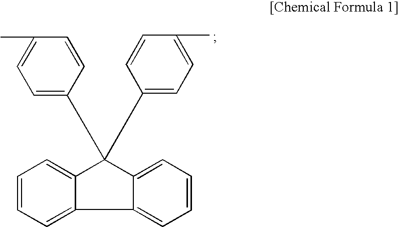
The present invention can provide an anion exchange type separation membrane used for direct liquid fuel type fuel cell, high in heat resistance, hard to deteriorate when using and capable of obtaining high battery output. A composite membrane used as the separation membrane for fuel cell can be obtained by using a porous film, composed of a hydrolysis resistant polyimide resin such as a polyimide resin having a fluorenylidene group in a main framework, as a substrate; optionally increasing water retention characteristics for example by applying a water-retentive resin to at least a part of a surface of the porous film; and then filling an anion-exchange resin such as a cross-linked hydrocarbon-based anion-exchange resin having a quaternary ammonium group as an anion exchange group into a void portion of the porous film.

Description

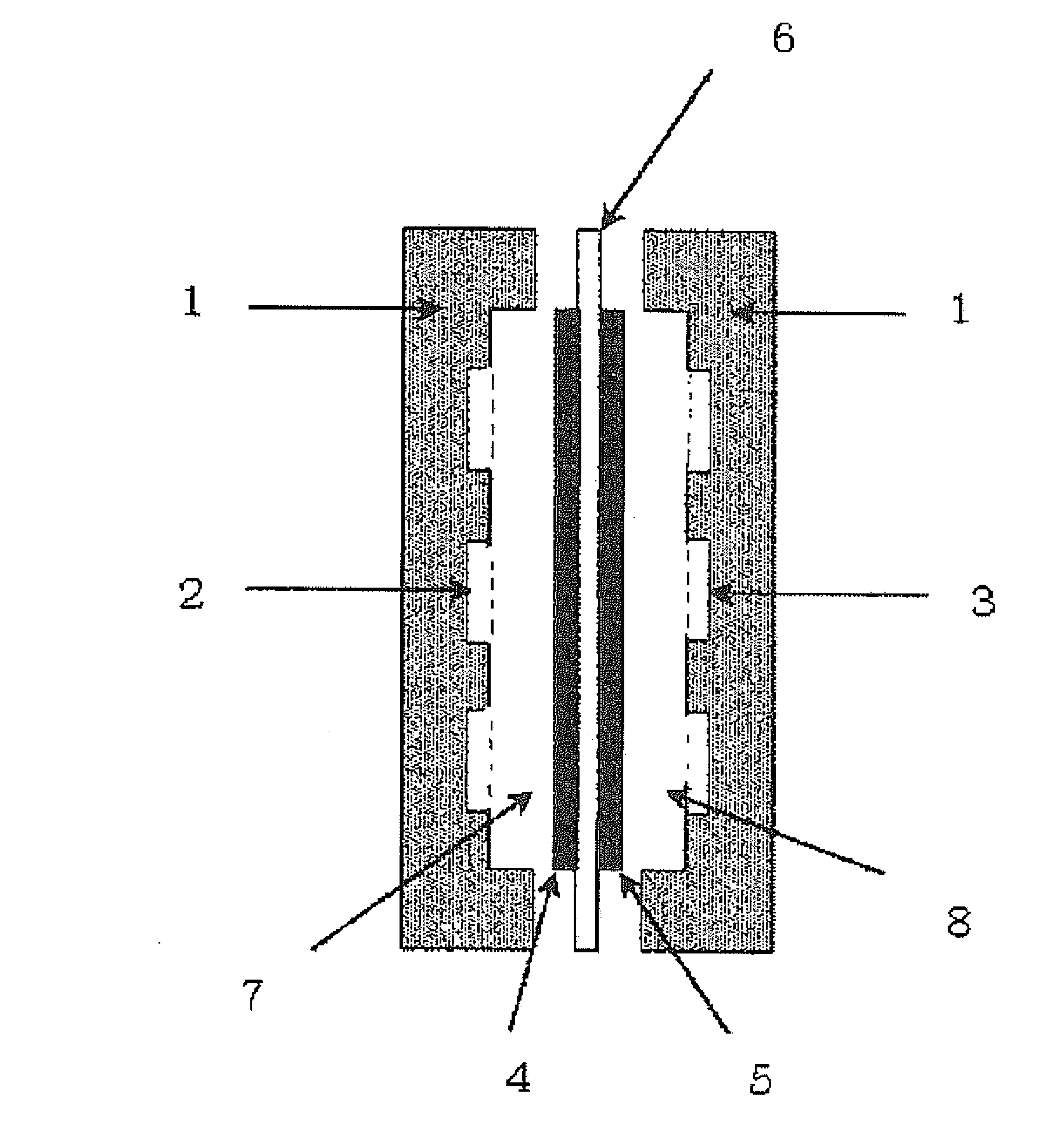
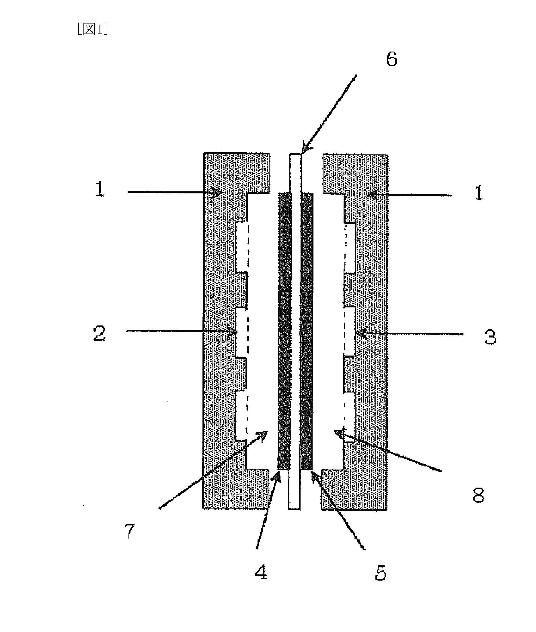
FIELD OF THE INVENTION[0001]The present invention relates to a separation membrane for fuel cell, specifically a separation membrane having an anion exchange group used for direct liquid fuel-typed fuel cell.DESCRIPTION OF THE RELATED ART[0002]A solid polymer type fuel cell is a fuel cell using a solid polymer, such as an ion exchange resin, as an electrolyte. The solid polymer type fuel cell has, as shown in FIG. 1, a basic structure wherein a space surrounded by cell bulkhead 1 having fuel gas flow hole 2 and oxidizing gas flow hole 3, respectively communicated with outside, is divided by an assembly in which a fuel chamber side gas diffusion electrode 4 and an oxidizing agent chamber side gas diffusion electrode 5 are bonded to both surfaces of a solid polymer electrolyte membrane 6 respectively, to form fuel chamber 7 communicated with outside via fuel gas flow hole 2 and an oxidizing agent chamber 8 communicated with outside via oxidizing gas flow hole 3. Note that the cell bul...

Claims


Application Information

Patent Timeline
Patent Type & Authority Applications(United States)
IPC IPC(8): H01M8/10H01M8/02
CPCC08G73/1042C08G73/1046C08G73/105C08G73/1067C08G73/1071C08L79/08Y02E60/521H01M2/1686H01M8/1009H01M8/106H01M8/1062H01M2300/0082H01M2/1653Y02E60/50Y02E60/10
Inventor MATSUI, SHINGOKAWAHARA, TAKEOFUKUTA, KENJIYANAGI, HIROYUKI
Owner TOKUYAMA CORP
Learn More