Reconfigurable measurement system utilizing a programmable hardware element and fixed hardware resources
Inactive Publication Date: 2003-08-28
NATIONAL INSTRUMENTS
24 Cites 139 Cited by
AI-Extracted Technical Summary
Problems solved by technology
Often, the field signals may comprise high common-mode voltages, ground loops, or voltage spikes that often occur in industrial or research environments which could damage the computer system.
In general, compile times for generating a hardware configuration program for an FPGA may take a lengthy time, e.g., many hours.
When targeting the hardware (i.e., the programmable hardware element)...
Method used
[0150] In addition to the creation of user specific I/O interfaces, RIO may provide for the timing and triggering of these interfaces, allowing for very flexible relationships between resources. For example, the user may configure one group of I/O to be sampled at one rate, and another group at a completely independent rate. This same flexibility may apply to starting, stopping, pausing, etc. of I/O operations.
[0210] Thus, in one embodiment, everything behind the I/O can be redefined as desired to implement a given functionality, i.e., only the physical I/O is static (e.g., more ADCs can't generally be added, unless a mixed signal FPGA, described below, is configurable to implement them). The configuration for the programmable hardware element 106 may be "tuned" to a specific application, and may therefore minimize incompatibilities between the application and system hardware.
[0232] Thus, the use of an FPGA 106 to implement digital logic in a measurement device provides a flexible solution to application specific digital logic requirements. Additionally, the use of a mixed signal FPGA extends the approach to include programmatically configurable analog components, which, in combination with the configurable digital logic, provides a broad, flexible solution approach to measurement and control system development. More specifically, various embodiments of the RIO system may provide improved I/O solutions for real time systems and applications (e.g., LabVIEW RT based applications), providing support, for example, for simultaneous sampling, synchronized AI, AO, DIO, and TIO (timed I/O), and balanced analog I/O, as well as providing a single point architecture. Additionally, RIO may facilitate use of a simplified register map, such as for interfacing with other systems. Finally, as noted above, RIO provides for customized functionality of measurement, control, automation, and simulation hardware, thereby providing the flexibility of software based systems with the performance of hardware.
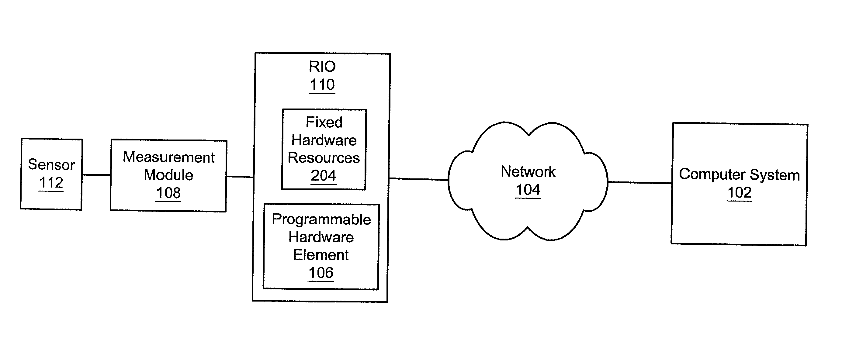
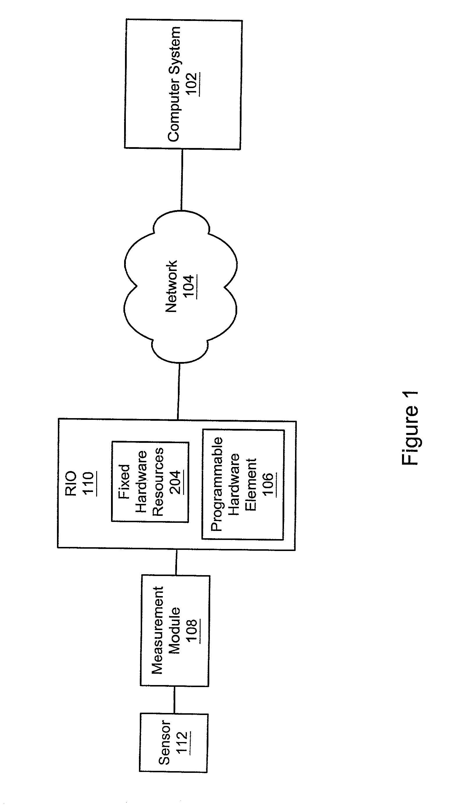
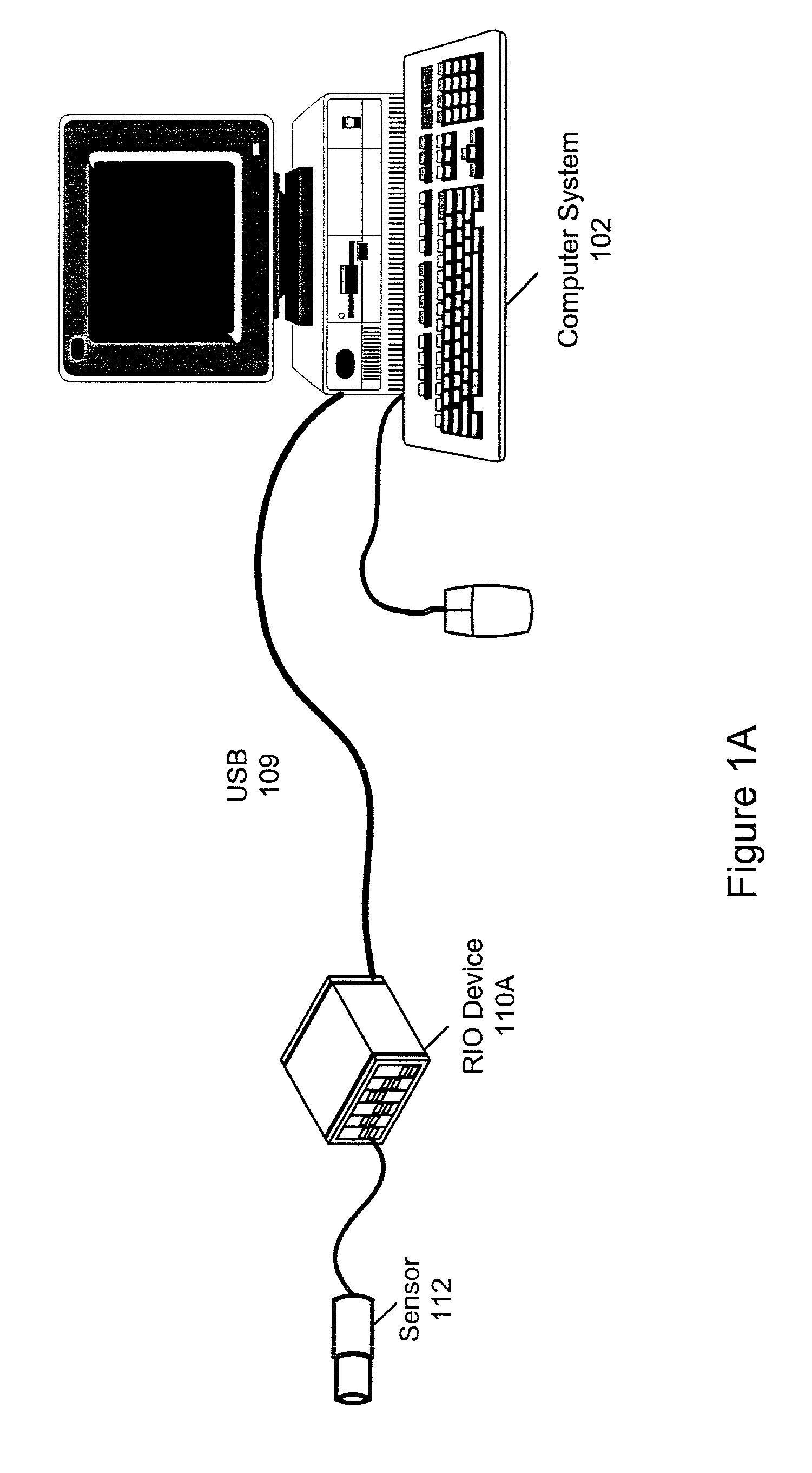
[0256] It should be noted that in various embodiments, the RIO 110 may be operable to perform other functions in addition to the adaptive interface functionality described above. For example, in one embodiment, the RIO 110 may include network control circuitry (or have a programmable hardware element configured to perform network control functions), and thus may comprise a networked measurement and control device, or a networked data acquisition device. In other words, the RIO unit 110 may comprise one or more of an Ethernet carrier, a USB carrier, and a wireless carrier (such as IEEE 802.11 Wireless Ethernet or Bluetooth), among others, to facilitate transmission of data over a network to external systems, e.g., the computer system 102.
[0268] In one embodiment, the digital I/O 720 may couple to a breakout backplane 704, for example, via parallel SPI buses 730, as shown, although other buses for coupling the I/O expansion devices to the RIO 110 are also contemplated. The breakout blackplane 704 may provide connectivity for a plurality of measurement module cards or cartridges 108, and may thereby be operable to facilitate external, synchronized, and conditioned I/O 750 for the measurement system. For example, each measurement module or cartridge 108 comprised in or on the breakout backplane 704 may be operable to couple to a sensor or actuator 112. Each measurement module 108 may also couple to the backplane 704. The breakout backplane 704 may then facilitate synchronization between the various measurement modules 108. Additionally, as described above, the measurement modules 108 may provide any of a variety of DAQ, measurement, and control functions, including signal conditioning and conversion, and thus external, synchronized, and conditioned I/O 750 capabilities may be included in this embodiment of the invention.
[0278] In contrast, it is contemplated that the RIO engine/architecture may be combined with all of the listed platforms 802, i.e., PXI platform 811, PCI platform 812, DAQPads platform 813, FieldPoint platform 814, small networked measurement nodes 815, and PDA/handhelds 816), as well as other platforms not shown, e.g., InfiniBand, USB, 1394/FireWire, etc. Note that use of the RIO engine/architecture facilitates combinations with RIO signal conditioning devices 110 and measurement modules 108, respectively, for signal conditioning functions 806, as shown. The RIO engine/architecture may also be used with any of the signal conditioning options 806 shown in FIG. 8, including SCXI, SCC, 5B, Fieldpoint/Bluebus, and other types of signal conditioning or measurement modules.
[0281] Thus, the use of measurement modules 108 and various RIO units 110 may provide complementary and overlapping functionality as compared to current approaches to development of measurement systems, and may also provide substantial cost, efficiency, and flexibility benefits. In particular, the use of RIO devices 110 and/or measurement modules 108 leverages semiconductor technology to deliver highly modular measurement, control, and signal conditioning/conversion functionality which may be reusable in many platforms, e.g., USB, Ethernet, FieldPoint, RIO, PDAs, etc., and which may lower risk and effort in supporting new platforms, such as wireless, CAN, etc.
[0340] Finally, as indicated in FIG. 14, the FPGA may include debug/simulation functionality which may facilitate design and debugging operations in a simulation environment on the host computer system 102, as described below with reference to FIGS. 15 and 16.
[0359] In 1604, the programmable hardware element 106 may be configured with a test feed-through configuration. The test feed-through configuration may be stored in host computer memory in a pre-compiled format, and thus may be quickly downloaded to the programmable hardware element 106. After configuration with the test feed-through configuration, the programmable hardware element 106 is operable to provide for communi...
Benefits of technology
0074] Thus, the use of one or more configuration wizards may provide an easy to use interface which allows the user or customer to configure or construct custom configurations for a reconfigurable system (i.e., the programmable hardware element in a RIO system). More specifically, a wizard may provide the user access to configurable RIO functionality without the user having to be familiar with a particular development environment, such as LabVIEW.
0075] Thus, the use of RIO devices in combination with a variety of platforms and computer systems provides a broad range of approaches for effi...
Abstract
A system and method for configuring a device to perform a function, where the device includes a programmable hardware element and one or more fixed hardware resources. A program is stored which represents the function. A hardware configuration program is generated based on the program, specifying a configuration for the programmable hardware element that implements the function, and usage of the fixed hardware resources by the programmable hardware element in performing the function. A deployment program deploys the hardware configuration program onto the programmable hardware element, where, after deployment, the device is operable to perform the function, where the programmable hardware element directly performs a first portion of the function, and the programmable hardware element invokes the fixed hardware resources to perform a second portion of the function. An optional measurement module couples to the device and performs signal conditioning and/or conversion logic on an acquired signal for the device.
Application Domain
Error detection/correctionMeasurement arrangements for variable +6
Technology Topic
Programmable hardwareComputer hardware +2
Image
Examples
- Experimental program(2)
Example
EXAMPLE
[0386] A customer wishes to implement a control loop with National Instruments LabVIEW RT for an algorithm and LabVIEW FPGA for the timing and triggering. A control wizard may query the user about the I/O structure: How many synchronous analog inputs, analog outputs, digital inputs, digital outputs, and counters are in the system? How many asynchronous channels are in the system?
[0387] After receiving user input answering these queries, the control wizard may script a diagram with just the I/O the customer needs, as well as the required controls and indicators. The customer may then focus on the LabVIEW RT control algorithm instead of low level I/O details. If the customer discovers later that further customization of the timing and triggering is needed, the LabVIEW FPGA diagram may be modified directly.
[0388] In one embodiment, wizards may only include support for rudimentary functionality. In other words, wizards for basic acquisition, control loops, hardware in the loop testing, etc., may be provided. In another embodiment, the wizards may provide broad functionality in their respective areas of application. For example, in one embodiment, an acquisition wizard may only support pre- and post-triggering. In another embodiment, the acquisition wizard may also support external conversion, hardware gating, and other more advanced functionality.
[0389] Thus, in one embodiment, configuration wizards may be provided for basic timing and triggering functionality, without a broad application focus. In another embodiment, application-specific wizards may be provided, possibly built on top of the timing and triggering wizards.
[0390] In one embodiment, a wizard may provide a palette of basic I/O components and allow the user to select a variety of components and configure them individually. In one embodiment, the wizard may provide substantially the same user experience for progressively more complex components. Thus, the available features selectable by the user include a combination of the simple I/O components and complex structures. In one embodiment, the wizard may be upgradeable with new features as they are developed. Thus, the wizard may allow the user to collect various blocks into a configuration, and to configure these blocks and the resulting configuration to the user's specific requirements.
[0391] In one embodiment, the wizard may be based on a standard configuration framework, such as National Instruments Workshops framework, and may host a configuration VI (Virtual Instrument) or diagram provided for each selectable feature. The diagrams of each selected feature may be combined (by the wizard) into a single diagram. In one embodiment, after the final diagram has been constructed or assembled, the wizard may contact a compile server automatically, and a compiler program, such as LabVIEW FPGA, may be used to create a hardware configuration program, e.g., a bit file.
[0392] Thus, the use of one or more configuration wizards may provide an easy to use interface which allows the user or customer to configure or construct custom configurations for a reconfigurable system (i.e., the programmable hardware element in a RIO system 110). More specifically, a wizard may provide the user access to configurable RIO functionality without the user having to be familiar with a particular development environment, such as LabVIEW.
[0393] FIG. 18--A Method for Configuring a RIO System Using A Configuration Tool
[0394] FIG. 18 is a flowchart of a method for configuring a reconfigurable system (i.e., a RIO system), according to one embodiment. The reconfigurable system preferably comprises a programmable hardware element and one or more fixed hardware resources coupled to the programmable hardware element. As noted above, in some embodiments, various of the steps may occur concurrently, in a different order than shown, or may be omitted. Furthermore, one or more additional steps may be performed as desired.
[0395] As FIG. 18 shows, in 1802, a graphical user interface may be displayed on a display which is useable for configuring the reconfigurable system. The graphical user interface may display fixed hardware resource icons corresponding to each of at least a subset of the fixed hardware resources.
[0396] In 1804, user input to the graphical user interface may be received which specifies a function. For example, the reconfigurable system may be a reconfigurable measurement system, and the function may be a measurement function. In other embodiments, the reconfigurable system may be one or more of a reconfigurable control system, a reconfigurable automation system, and a reconfigurable simulation system, and the function may correspondingly be one or more of a control function, an automation function, and a simulation function.
[0397] As noted above, the user input to the graphical user interface may include text or numerical input, menu or button selections, iconic selection, drag and drop, or any other technique of entering data with a GUI. In one embodiment, the received user input may be regarding one or more of the fixed hardware resources required by an application to perform the function. The received user input may further specify timing and triggering requirements of the application with respect to the specified fixed hardware resources.
[0398] In one embodiment, an appearance of respective fixed hardware resource icons may be modified as the corresponding fixed hardware resources are allocated to perform functions in response to the user input. In other words, the modified appearance of the respective fixed hardware resource icons may visually indicate to the user that the corresponding fixed hardware resources have been allocated for use.
[0399] In another embodiment, an icon corresponding to the programmable hardware element may be displayed. Furthermore, proposed configurations of the programmable hardware element may be displayed interactively in response to receiving the user input. Thus, the user may be provided visual feedback regarding the configuration currently specified.
[0400] In 1806, a hardware configuration program may be generated based on the user input, where the hardware configuration program is deployable on the reconfigurable system. In other words, the hardware configuration program may be loadable onto the programmable hardware element of the RIO device 110, thereby configuring or programming the RIO device 110 to perform the specified function.
[0401] In one embodiment, generating the hardware configuration program may include generating a description file which identifies resources and features to perform the function indicated by the user, generating a program from the description file, generating hardware description language (HDL) code from the program, and generating the hardware configuration program from the HDL code. In one embodiment, the program is a graphical program.
[0402] Finally, in 1808, the hardware configuration program may be deployed on the programmable hardware element, where the hardware configuration program specifies use of one or more of the fixed hardware resources in performing the specified function. Said another way, after deploying the hardware configuration program onto the programmable hardware element, the reconfigurable system, including the one or more fixed hardware resources, is operable to perform the function.
[0403] In one embodiment, the programmable hardware element is a field programmable gate array (FPGA), and the hardware configuration program is a program binary file for the FPGA.
[0404] After the programmable hardware element has been configured with the hardware configuration program, the hardware configuration program may be executed on the programmable hardware element to perform the function. In one embodiment, the programmable hardware element may execute a first portion of the function, and the programmable hardware element may invoke operation of one or more of the fixed hardware resources to perform a second portion of the function.
[0405] FIGS. 19A-19E--Example Configuration Wizard Interface
[0406] FIGS. 19A-19E illustrate various example displays of a configuration wizard, according to one embodiment. It should be noted that these displays are meant to be illustrative only, and are not intended to limit the form or function of a configuration wizard to those shown.
[0407] FIGS. 19A and 19B--Wizard User Interface
[0408] FIGS. 19A and 19B illustrate one embodiment of a user interface of a configuration wizard. As FIGS. 19A and 19B show, in one embodiment, the interface may include a blocks section or panel indicating the various components or control structures the user may configure, such as digital I/O, analog input, analog output, timed loop, and free running looping, among others. In one embodiment, the user may select or click a particular block to activate the configuration panels for that component or control structure.
[0409] In one embodiment, the interface may include an icon strip, shown between the blocks panel and a main panel. Each icon represents a configured component or control structure corresponding to one of the blocks in the block panel, a listed above. In another embodiment, each icon in the icon strip may represent a step or function of the function being created. Thus, as the user selects and configures functions, corresponding icons are added to the icon strip. It should be noted that each time a block is selected indicating a new function, an icon may be added to the icon strip. In one embodiment, when a user selects (clicks) an icon in the icon list, the configuration wizard may present one or more panels corresponding to that component or control structure, thereby allowing the user to quickly access any function specification for review, revision, replication, or deletion.
[0410] In the example shown in FIG. 19A, a digital I/O component has been selected, and so the main panel presents digital I/O configuration parameters which may be set by the user. In one embodiment, default values for each component may be provided by the wizard which may be over-ridden by user input.
[0411] FIG. 19B illustrates the use of the wizard to configure components in the free running loop. As FIG. 19B shows, analog input 2 has been selected for inclusion in the loop.
[0412] After the user has set the parameters for the selected components and/or control structures, the wizard may generate a diagram or VI, preferably via a scripting language. Example diagrams are described below with reference to FIGS. 19C-19E.
[0413] FIGS. 19C-19E--Wizard User Interface: Scripting Diagrams
[0414] FIGS. 19C-19E illustrate the process whereby the wizard generates a diagram or VI representing the specified functionality of an application. As noted above, the wizard preferably generates the diagram via a scripting process, although other means of generation are also contemplated, including compilation, look-up tables, etc.
[0415] FIG. 19C illustrates the placement of timing loops onto the diagram. Specifically, a timed loop and a free running loop are each added to the diagram. Note that in this case the loops are not nested.
[0416] FIG. 19D illustrates the placement of I/O components onto the diagram. As FIG. 19C shows, an analog input component is added to both the timed loop and the free running loop. Additionally, an analog input is added to the timed loop, along with two DIO inputs. Thus, based on the user input configuration information, the wizard may generate a diagram or VI which implements the functionality specified by the user. FIG. 19E shows the state of the diagram after the loops have been added and populated with the digital and analog I/O components. The addition of these structures and components to the diagram may result in a dynamically created front or main panel, as shown in FIG. 19F, described below.
[0417] FIG. 19F illustrates a dynamically created front or main panel of the wizard graphical user interface. As shown in FIG. 19F, the main panel may include a configuration field for each of the added analog and digital I/O components whereby the user may view and modify the parameter values for each component.
[0418] After the diagram has been finalized (saved), the diagram may be converted or exported to a bit file, e.g., a hardware configuration program. In one embodiment, the diagram may be converted to a graphical program diagram in another development environment, such as LabVIEW. Thus, a wizard may be allow a user to specify a function or task and generate a graphical program implementing the function or task.
[0419] Where a reconfigurable system comprises a programmable hardware element coupled to one or more fixed hardware resources, as described above, the system may be configured by a wizard in the following manner:
[0420] Initially, the wizard may display a graphical user interface on a display (i.e., a computer display) which is useable for configuring the reconfigurable system, where the graphical user interface displays fixed hardware resource icons corresponding to each of at least a subset of the fixed hardware resources. In other words, the wizard may represent some or all of the fixed hardware resources by graphical icons, referred to as fixed hardware resource icons.
[0421] The wizard may then receive user input specifying a function, as described above. The user input may include selection of components and/or control structures, as well as selection or setting of component or control structure parameter values. In one embodiment, receiving user input may include receiving user input regarding one or more of the fixed hardware resources required by an application to perform the function, as well as receiving user input specifying timing and triggering requirements of the application with respect to the specified fixed hardware resources. Said another way, the wizard may receive user input specifying resources required by an application to perform a function, as well as user input specifying timing and triggering requirements of the application with respect to the specified resources. In one embodiment, specifying resources may comprise selecting one or more of hardware and software resources, and indicating configuration settings for the resources.
[0422] In one embodiment, receiving the user input specifying the function may be performed by a server computer system. Additionally, in one embodiment, prior to the server computer system receiving the user input, a user (client) computer system may access the server computer system over a network. In other words, the user may engage the configuration wizard over the Internet by using the client computer system to access a vendor's server computer system, and use the configuration wizard, as described above.
[0423] A hardware configuration program may then be generated which is deployable on the reconfigurable system, as described in detail above. For example, in one embodiment, generating a hardware configuration program may comprise generating a description file identifying resources and features to perform the function indicated by the user, generating a program from the description file, generating hardware description language (HDL) code from the program, and generating the hardware configuration program from the HDL code. As described above, the hardware configuration program is usable to configure the programmable hardware element comprised in the reconfigurable system to perform the function. In one embodiment, the program generated from the description file may be a graphical program, such as a LabVIEW graphical program.
[0424] Configuration Storage and Matching
[0425] In one embodiment, the host and/or development environment may maintain a cache for storing one or more pre-compiled hardware configuration programs (configurations). For example, a library of such pre-compiled configurations may be developed representing common measurement tasks. Additionally, new configurations developed in response to new user specified requirements may be stored, i.e., may be added to the original library. By storing such pre-compiled configurations, the number of configurations developed from scratch in response to new user requirements may be minimized.
[0426] In one embodiment, in response to user input specifying a measurement task, a pre-compiled configuration may be selected from the stored configurations in the following manner. First, a determination may be made as to whether there is a pre-compiled configuration that precisely matches the customer's requirements (task definition). If such a match is found, the configuration may be retrieved and provided to the user.
[0427] If a direct match is not found, then a search may be made for a configuration which provides a strict superset of the required functionality, i.e., one that has all the requirements and more. Although the superset configuration provides more functionality than the user requires, the configuration meets the requirements, and may not take much more time to compile. Therefore, (after confirmation by the user, if such an option is enabled), the superset configuration may be retrieved and provided to the user. It is noted that compilation of a configuration generally requires much more time than selection of a configuration, thus, because the more complex configuration is pre-compiled, the selection of a larger configuration may not require substantially more time than a smaller configuration. Having a larger configuration may make the interface more complex, but the user can easily ignore those functions not needed by the user.
[0428] In one embodiment, if a suitable superset configuration is not found, or if the user chooses not to use the superset configuration, a search may be made for a "closest"configuration, i.e., a configuration with similar, although not quite the same functionality specified by the user. For example, a "closest" match configuration may have the same number of digital I/O but may have one less analog channel. If this is acceptable to the user, then the configuration may be selected and provided to the user.
[0429] Alternatively, if an exact configuration is required by the user, the configuration may be developed as described above, and provided to the user.
[0430] After the hardware configuration program is generated (or selected), the hardware configuration program may be deployed on the programmable hardware element, where the hardware configuration program specifies use of one or more of the fixed hardware resources. In other words, the hardware configuration program may specify not only the behavior or the programmable hardware element, but may also specify how the one or more fixed hardware resources are to be used by the programmable hardware element in performing the specified function. After the hardware configuration program has been deployed, the reconfigurable system may be operable to perform the function.
[0431] In one embodiment, after the hardware configuration program has been deployed on the programmable hardware element, the hardware configuration program may be executed on the programmable hardware element to perform the function. Executing the hardware configuration program on the programmable hardware element may include the programmable hardware element executing a first portion of the function, and the programmable hardware element invoking operation of one or more of the fixed hardware resources to perform a second portion of the function. In other words, different portions of the hardware configuration program (and therefore, the function) may be directed respectively to performing operations directly on the programmable hardware element, and to operation of one or more of the fixed hardware resources coupled to the programmable hardware element.
[0432] In one embodiment, the wizard may modify an appearance of respective fixed hardware resource icons as the corresponding fixed hardware resources are allocated to perform functions in response to the user input, where the modified appearance of the respective fixed hardware resource icons visually indicates to the user that the corresponding fixed hardware resources have been allocated for use. For example, selected fixed hardware resource icons may be "grayed out" on the display, indicating that the corresponding fixed hardware resource is already being used, thus preventing the user from over tasking a given resource.
[0433] In one embodiment, the wizard may display an icon corresponding to the programmable hardware element, and interactively display proposed configurations of the programmable hardware element in response to receiving the user input. Said another way, the wizard may graphically illustrate the current configuration of the programmable hardware element as a result of the user specified parameters, components, resources, etc.
[0434] In one embodiment, the reconfigurable system may be a reconfigurable measurement system, and the function may be a measurement function. In other embodiments, the reconfigurable system may be one or more of a reconfigurable control system, a reconfigurable automation system, and a reconfigurable simulation system, and the function may be a corresponding one or more of a respective control function, an automation function, and a simulation function.
[0435] As noted above, in one embodiment, the programmable hardware element may be a field programmable gate array (FPGA), and the hardware configuration program may comprise a program binary file for the FPGA.
[0436] Thus, when the reconfigurable system comprises a reconfigurable measurement system, the method may include the wizard displaying a graphical user interface on a display which is useable for configuring the reconfigurable measurement system, where the graphical user interface may display icons corresponding to each of at least a subset of the fixed hardware resources. The wizard may then receive user input specifying a measurement function, and generate a hardware configuration program, where the hardware configuration program is deployable on the reconfigurable measurement system. Finally, the hardware configuration program may be deployed on the programmable hardware element, where the hardware configuration program specifies use of one or more of the fixed hardware resources. Additionally, receiving the user input may include receiving user input regarding one or more of the fixed hardware resources required by an application to perform the function, as well as timing and triggering requirements of the application with respect to the fixed hardware resources. As mentioned above, after deploying the hardware configuration program, the reconfigurable system may be operable to perform the measurement function.
[0437] FIG. 20--A Hardware Block Module Generator
[0438] As described above, in the course of generating a hardware configuration program from user specifications, a graphical program, such as a LabVIEW diagram or VI, may be created, analyzed and converted into a form suitable for deployment on the programmable hardware element. As is well known in the art, many graphical programs may include nodes or elements which themselves represent other graphical programs or diagrams. In the context of LabVIEW, these sub-programs are referred to as sub Vis or blocks.
[0439] In such a conversion, when a sub VI is encountered on a LabVIEW diagram, one approach is to explore the sub VI and automatically generate a corresponding hardware configuration. Alternatively, custom logic that the user has developed may be used to convert the sub VI. In one embodiment, the user may create such custom logic through the use of module generators. To create a module generator, the user may start by using a configuration tool, such as the configuration wizard described above, to set up an API to the corresponding hardware component. A screen shot of one embodiment of this tool is shown in FIG. 20.
[0440] Referring to FIG. 20, in the first field of the block generator tool, a "Wrapper VI Path" may define an API to a corresponding hardware component. After selecting a VI, "Static Implementation Code" may be started with a port list for the hardware component. If the hardware component is a purely static implementation, the user may simply type VHDL code into the "Static Implementation Code" tab and then hit "Save Modifications to Module Generator" and be done. The options tab may allow the user to request resources off the board to be used in the selected component. If the resource is used elsewhere, a backend program may automatically arbitrate between competing accessors, i.e., the components which are concurrently configured to use the selected component.
[0441] A powerful feature of module generators may become apparent when the code generated is not entirely static. In other words, the VHDL created may vary depending on inputs to the block or sub VI (whether the inputs are constant or not), the structure of the parent diagram, and/or information on the front panel of the sub VI that defines the class of the object (this may be useful for arbitration options or other options that apply to a component everywhere in a particular application). In one embodiment, the dynamic behavior of the hardware created may be controlled using the G language itself. The module generators may just be VIs which the user can access and modify at will. An example block diagram is illustrated in FIG. 21, described below.
[0442] FIG. 21--Example Block Diagram
[0443] FIG. 21 illustrates a block diagram or VI generated by a module generator, as described above. In other words, the VI of FIG. 21 is the result of a dynamic code generation process. The interesting parameters for dynamic code creation are the Node Refnum (a reference to the node on the block diagram) and the VI Refnum (a reference to the VI that is being used as a sub VI).
[0444] In one embodiment, the module generator framework may be pseudo-object oriented. In one embodiment, a set of VIs may be automatically generated for a specified component. For example, in one embodiment, the module generator VIs automatically created may be as follows:
[0445] 1. Constructor--Allows the user to initialize instance data that is passed between all the following VIs, and may also support the use of multiple languages, where the constructor specifies the possible languages and the Get Mod Info VI, described below, gets passed which language should be implemented, e.g., "VHDL".
[0446] 2. Get Mod Info--Allows the user to request hardware resources (ADCs, DACs, DIO lines, etc). In one embodiment, this VI may also tell the backend how many cycles the block takes to execute and other information the backend may use to optimize surrounding logic.
[0447] 3. Get Mod Implementation--Allows the user to specify the implementation for the hardware component.
[0448] 4. Get Mod Declaration--Allows the user to specify a custom declaration for his component. In one embodiment, a default value may be provided by the backend.
[0449] 5. Get Mod Instantiation--Allows the user to specify a custom instantiation for the selected component. In one embodiment, a default value may be provided by the backend.
[0450] 6. Destructor--Allows the user to clean up any instance data passed between the above VIs.
[0451] These VIs may be called in sequence from the backend when a matching component is found on the users original diagram.
[0452] Communication
[0453] Communication is important for distributed applications. For RIO, the communication is between the board and the host, or between a measurement module 108 and RIO 110, or between hardware glue and a soft-core instantiated on the programmable hardware element 106, e.g., the FPGA.
[0454] Automatic API Generation
[0455] Many times an application (VI) developed using a hardware configuration development environment, e.g., LabVIEW FPGA, is part of a larger system. Therefore, in one embodiment, an API may be automatically generated for the user for accessing the hardware application from a host. This wizard application may list all resources used in a user's application (controls and indicators on the front panel, DMA channels, and interrupts) and give the user the option to not create an API entry for that particular channel. When the user is satisfied, he may simply hit a button and the wizard application may generate a palette of VIs for controlling and communicating with his application on our board. The user may then use these VIs in a larger system on the host. The basic services offered by the automatically generated API may include:
[0456] 1. Open--Reserve resources, open references, etc.
[0457] 2. Close--Opposite of open.
[0458] 3. Download--Deploy a configuration to the board.
[0459] 4. Control--Control the execution of the deployed configuration (run, stop, halt, etc)
[0460] 5. Access--Channels and ports that hide the implementation of registers, interrupts, and DMA. Automatic synchronization of data may be supported. Alternatively, the user may build synchronization into his application.
[0461] One problem which may arise with this automatic interface generation is that it may be strongly tied to the application created in hardware. In other words, if the application changes, the API may change, which means the host based application may require change as well. Therefore, in one embodiment, the user may be allowed to group particular resources into classes where all members of a class have exactly the same API. Subclasses may implement inheritance for extending the API.
[0462] The particular resources here may be communication channels and ports. These channels and ports may be uni- or bi-directional but are preferably always visible and locatable from both sides. The concept of channels and ports may hide the particular implementation of registers, interrupts, dma, and synchronization logic. The channel or port may be configured to take advantage of a particular communication method or synchronization method. For synchronization, channels/ports may be grouped together into one synchronized group. In a further embodiment, interface templates may be provided such that the user may just modify the template for a particular application but needn't modify the API. Then as long as the user's operations remain inside the framework, the same API will exist. These mechanisms may allow the policy of the implementation to change while keeping the same API.
[0463] In one embodiment, the `calling of VIs` may be distributable between different machines and boards, thereby providing communication, synchronization, and system level design capabilities to the development environment, e.g., LabVIEW.
[0464] Embedded Microcontroller Interfacing
[0465] It is possible to implement microcontrollers inside FPGAs. These can be either hard or soft cores depending on whether they are implemented using custom silicon or not. The soft cores are reconfigurable but the performance is not as great. In one embodiment, interfacing to one of these microcontrollers may be performed in a similar way to interfacing to the host as described above under the section titled "Automatic API generation". Potentially, the same API generation mechanism could be used for hardware-hardware, software-software, and hardware-software interfaces.
[0466] Arbitration for Shared Resources
[0467] In one embodiment, resources may be used more than once in an application. Resources are usually hardware (ADCs, DACs, DIO lines, etc), but may also be processing elements or sub VIs. If resources are used more than once an arbiter may need to be placed between the users of the resource and the resource. The arbiter may be responsible for serializing access to the resource. In one embodiment, the arbiter may be implemented as a series of flip flops connected in a ring with enables to move from one accessor to the next. Each flip flop may take one cycle, so a worst case delay through an arbiter may be equal to the total number of possible accessors. Generally, just one accessor is active at a particular time, and so a small circuit may be included that determines whether there is only one accessor. If there is only one accessor, access may be granted and the flip flop state machine with its variable delay may be ignored. A simple diagram illustrating this approach is shown in FIG. 22, described below.
[0468] FIG. 22--Arbitration of Access to a Component
[0469] FIG. 22 illustrates an approach for determining if there is only one accessor is general knowledge for figuring out if a number is a power of two:
[0470] If( requests && !(requests & (requests-1)))
[0471] Requests is a power of 2 and so there is a single accessor.
[0472] Else
[0473] There is more than one simultaneous access so use the round robin flip flop state machine.
[0474] This design has two useful aspects. For one, the round robin flip flop state machine is very simple and so is very likely to meet static timing requirements no matter how many possible accessors there are (within reason). Additionally, the single accessor check improves the performance for non simultaneous accesses at a minimal logic cost.
[0475] Hardware State and Logic Sharing
[0476] Logic takes up space on an FPGA. Multiple instances of much logic could possibly share the same logic for space savings assuming the timing requirements are not tight. In this case the logic may become similar to a hardware resource to which access may be arbitrated. In doing this, some parallelism available in hardware may be lost because access to a resource (logic) is being serialized but space may be saved. Sharing access to logic is similar to non reentrant sub VIs in LabVIEW.
[0477] One problem with sharing access to sub VIs is state must sometimes be saved from one execution of a sub VI to the next from the same instance on a parent block diagram. This may be done in LabVIEW using reentrant sub VIs with front panel controls and indicators that are unconnected and also uninitialized shift registers. One approach using LabVIEW FPGA is to use registers to hold state information. These are behind the scenes, in that the user still uses shift registers and front panel controls. A more efficient implementation for shared sub VIs may be to use block RAM inside or outside the FPGA to store the state information. A reference may then used for every instance of a sub VI to pull out the correct state information. In the first approach all the state information is in effect being passed in and out of the sub VI. With the second approach only the reference is passed. The second approach may be inefficient for non shared sub VIs, but for shared sub VIs may be an efficient solution.
[0478] Simulation Environment
[0479] Simulation environments are useful to figure out how a system will respond in certain situations before implementing them. This is particularly important in hardware configuration development environments, e.g., LabVIEW FPGA, because the compile times are typically very long.
[0480] System Level Simulation
[0481] If the user develops a hardware application for incorporation into a larger system, as mentioned above, it may be desirable to simulate the entire system before compiling the hardware application. If everything is written in a graphical programming language such as LabVIEW this may not be difficult. All API VIs just need to have special simulation logic that gets executed when in simulation mode. For front panel register access, the simulation target can just use VI server calls to set/get values from the front panel. For DMA, the API VIs can use LabVIEW Queues. For Interrupts, the API VIs can use LabVIEW occurrences.
Example
[0482] Example RIO Configurations
[0483] The configurations for the RIO board are created from a collection of I/O components. These I/O components can be grouped in different ways to create configurations for focused applications. The I/O components may include typical DAQ like interfaces such as analog input, analog output, digital I/O, and timing I/O. The grouping provides the timing and triggering layer on top of these components, which may include free running resources, fully synchronous mixed I/O, hardware triggered operations, and more.
[0484] The configurations for the RIO board can be organized into a small number of classes, with minor permutations within each class. An example configuration class would be "post trigger", with permutations including SW triggered, HW triggered, etc.
[0485] Low Level Components
[0486] The primary I/O components are low level and directly access the hardware I/O. They are used for the basic analog input, analog output, and digital I/O interfaces.
[0487] 1. Analog Input
[0488] This component initiates an analog to digital conversion from an ADC. It returns the result of the conversion. This component tends to exist in timed loops, but can also be used in free running applications.
[0489] 2. Analog Output
[0490] This component writes a value to a DAC and initiates the digital to analog conversion. It returns no data. This component is commonly used for continuous and discrete output, existing in both timed and free running applications.
[0491] 3. Digital Input/Output
[0492] This is really a collection of components that act on a single hardware resource. A given digital line can be used for input, output, or bidirectional applications. This component is more commonly used in static DIO applications or as a building block for higher level functionality, with some timed applications.
[0493] High Level Components
[0494] The DIO lines are the resources most commonly used to build higher level I/O components. These are components that interface to digital signals but need some amount of logic or processing to be meaningful, with the best example being counter applications. Note that it is possible to use the analog components for these applications, it is simply not as common. There are many more minor and major variations than listed below, but these are very common examples.
[0495] 1. Event Counter
[0496] This high level component counts active edges on a digital input. It typically offers polarity control over the incoming signal, a means to control the start and stop of counting, and a readable register with the counter data. When used in a timed loop application, this counter typically returns the number of counts during the previous loop iteration.
[0497] 2. Period Counter
[0498] This high level component counts the time between active edges on a digital input. It typically offers polarity control over the incoming signal, a means to control the start and stop of counting, and a readable register with the counter data. When used in a timed loop application, this counter typically returns data for the most recent measured period.
[0499] 3. Semi Period Counter
[0500] This high level component counts the time between opposite edges on a digital input. It typically offers polarity control over the incoming signal, a means to control the start and stop of counting, and a readable register with the counter data. When used in a timed loop application, this counter typically returns data for the most recent measured period.
[0501] 4. Quadrature Decoder
[0502] This high level component increments or decrements based on two digital inputs. It typically offers polarity control over the incoming signals, a means to control the start and stop of counting, and a readable register with the counter data. When used in a timed loop application, this counter typically returns the final counter value during the previous loop iteration.
[0503] 5. PWM Input
[0504] This high level component counts the high and low times of a pulse train. It typically offers polarity control over the incoming signal, a means to control the start and stop of counting, and a readable register with the counter data. When used in a timed loop application, this counter typically returns data for the most recent measured high and low periods.
[0505] 6. PWM Output
[0506] This high level component generates a pulse train with controllable high and low times. It typically offers polarity control over the generated signal, a means to control the start and stop of generation, and two writeable registers for period data. When used in a timed loop application, this counter is typically configured to run at a multiple of the loop rate for synchronous behavior.
[0507] Grouping of Components
[0508] The components by themselves do not provide much functionality. It is the grouping of the components in structured wrappers that define a particular configuration. These wrappers provide the timing and triggering of the components as well as the interface to the host diagram. These wrappers can be grouped into classes of functionality.
[0509] 1. Free Running
[0510] This configuration resembles a PLC in that it continuously samples and updates it's I/O as fast as possible. The input registers always contain the most recent data, and can be read at any time. The output registers can be written at any time, and the outputs will be updated as soon as possible. It is the simplest of the configurations in that there is no real timing, triggering, or data transfer synchronization issues for the customer.
[0511] Recommended Permutations
[0512] Different counter I/O combinations
[0513] 2. Continuous Timed Loop
[0514] This configuration provides a single timed loop for all synchronous resources. This is well suited to control loops with fully correlated I/O. The host is notified when it is time to access the I/O resources.
[0515] Recommended Permutations
[0516] SW & HW triggered
[0517] Mixes of synch/asynch DIO
[0518] Mixes of counter I/O
[0519] Different transfer mechanisms (Poll, Interrupt, DMA)
[0520] 3. Post Trigger Acquisition
[0521] This configuration provides the typical post triggered data acquisition functionality. A fixed number of points will be acquired when a SW or HW trigger is received. The same behavior is provided in different combinations for the other resources.
[0522] Recommended Permutations
[0523] Single and independent loops per resource type
[0524] SW & HW triggered
[0525] Mixes of synch/asynch DIO
[0526] Mixes of counter I/O
[0527] Different transfer mechanisms (Poll, Interrupt, DMA)
[0528] 4. Pre Trigger Acquisition
[0529] This configuration provides the typical pre triggered data acquisition functionality. A minimum number of pre trigger points will be acquired, and a post trigger will cause a fixed number of remaining samples to be taken. Note that there is not a comparable model for the output resources.
[0530] Recommended Permutations
[0531] Single and independent loops per resource type
[0532] SW & HW triggered
[0533] Mixes of synch/asynch DIO
[0534] Mixes of counter I/O
[0535] Different transfer mechanisms (Poll, Interrupt, DMA)
[0536] It should be noted that the above are meant to be illustrative examples of RIO configurations, and are not meant to limit the scope or form of configurations usable in the RIO system. Other features which may be considered configuring the RIO system 110 include, but are not limited to, other I/O features such as the number of channels, resolution, rates, protection, range, simultaneity and/or synchronization, and enhanced I/O functionality; timing models, including continuous, post trigger, and independent loops; signal conditioning, e.g., sensor interface; form factor, e.g., PXI, PCI, standalone, etc.; and environmental conditions, such as vibration, temperature range, humidity, among others.
[0537] FIGS. 23A and 23B--Configuration Generation
[0538] There are a number of ways in which a configuration may be generated for a user. In one embodiment, the user may select from a set of pre-built configurations, for example, maintained by a vendor. In this embodiment, the user may select the configuration which most closely matches requirements for the desired task. For example, the set of pre-built configurations may focus on common configurations, including base I/O types such as AI, AO, DI, and DO, as well as derived I/O types including counters, timers, period measurement, and frequency measurement. In a preferred version of this embodiment, all of the I/O may be timed, and basic triggering is supported. A host interface may be memory mapped and exported as registers. For example, a set of registers may serve to show the state of the hardware, and allow the software to write new values or command actions by setting appropriate bits in the register set. A user may initiate a command action by setting one or more bits, and the system may responds by performing a specified action. In one embodiment, a host interface may be provided for each application development environment (ADE). Additionally, in one embodiment, each configuration may be defined by a G diagram, which may also serve as documentation for the configuration.
[0539] In another embodiment, the hardware software boundary may be viewed as an interface between two objects that exchange messages. These messages may be either method invocations or set/get of attribute values. A standard interface may be defined that permits generic software-hardware calls. In one embodiment, the register set may be organized such that a first read starts a call, and if completed, returns an error code or status; if not completed the call may return an ID of the buffer in which the rest of the transaction will take place. If the hardware allows multiple threads to access the object, then the ID may be returned in the first call as well. The caller may pass and receive data in the buffer. Finally, after a sequence of reads and writes, the status returned may be completed on the last read. The code for the host interface (proxy), as described above, may be generated by a host interface generator executing in the development environment. In this manner, synchronization functionality may be provided while minimizing overhead.
[0540] As described above, based on a LabVIEW FPGA diagram a host interface may be generated that provides access to some or all of the configurable aspects of a VI or object. In various embodiments, the generated host interface may be static or dynamic, i.e., it may be generated with specialized and optimized code to interface with one specific VI or object (static), or with multiple Vis or objects (dynamic). In the static case, communication and associated overhead between the host and the VI or object may be minimized. However, changes made to the VI or object may require corresponding changes to the application and/or the generated interface (register set). In one embodiment, an application target manager (as part of the ADE) may be used to help the user manage these target-related changes. For example, the target-specific host interface VIs (or text-based code) in the application may be marked with a special tag, allowing the application target manager to track such changes and update the application as necessary.
[0541] In one embodiment, tools may be provided to the user to configure the board. For example, tools may be provided to locate the board (such as in a network), to download a configuration to the board, or to determine and locate measurement resources, among others. Additionally, tools may be provided to program the board, including tools to access the interface (registers) on a board for a given configuration. In a further embodiment, the user may make modifications to the selected pre-built configuration to more closely match the requirements.
[0542] FIG. 23A illustrates one example of a breakout of the responsibilities of the main system components of a RIO based system using this approach. As FIG. 23A shows, in one embodiment, RIO hardware 110 may provide timing, I/O, power on states, etc., while a controller 2302, such as LabVIEW RT, may provide algorithmic functionality, such as inline processing, control, and determinism (prescribed functionality). At runtime a host 102, e.g., a Windows based host, may optionally be present. At runtime the host may provide a GUI (graphical user interface), and supervisory behavior, among other host functions. As shown, the host 102 is the highest-level component of these primary system components, and communicates with the controller 2302, which is the mid-level component. The controller 2302 in turn communicates with the RIO unit 110, which is the low level system component, i.e., is the closest to the phenomenon being measured, controlled, etc. The fact that the presence of the host 102 at runtime is optional means that after the hardware configuration program has been created and deployed on the RIO unit 110, the presence of the host (the computer system 102) may not be required for the system to perform the specified measurement and/or control function.
[0543] In another embodiment, the user may build a configuration from pre-defined blocks (configuration components), diagrams, or software modules using a configuration wizard, described above, to specify and assemble the configuration from the pre-defined blocks. In other words, the wizard may allow the user to select pre-defined blocks to build a custom configuration for the user's application. In one embodiment, the wizard may be used by the vendor to build the pre-built configurations mentioned. In one embodiment, a host interface may be generated to match the user-defined configuration. Similarly, host interfaces may be generated for each of the pre-built configurations mentioned above in the same manner.
[0544] In yet another embodiment, the user may build a configuration using a development environment and user defined blocks, diagrams, or software components. For example, the user may create the configuration using user defined blocks based on the G graphical programming language, from National Instruments. In other words, the user may create G diagrams to define blocks. In one embodiment, these user-defined blocks may then be used by the wizard mentioned above as pre-built blocks. Thus, in one embodiment, an entire configuration may be defined with a G diagram. As mentioned above, a host interface may be generated to match each configuration.
[0545] FIG. 23B illustrates another example of the breakout of the responsibilities of the main system components of a RIO based system using this approach (user-defined blocks). As FIG. 23B shows, in this embodiment, the RIO hardware 110 may provide timing, I/O, power on states, etc., as well as algorithmic functionality, such as inline processing, control, and determinism (prescribed functions). Optionally, at runtime, the controller 2302, (e.g., LabVIEW RT) may provide additional algorithmic functionality, as described above. Thus a first portion of a graphical program may be deployed on a processor and memory (e.g., LabVIEW RT), and a second portion of the graphical program may be deployed on a programmable hardware element (e.g., LabVIEW FPGA). The host 102 may provide a development environment, a user interface which may provide configuration capabilities, a GUI (graphical user interface), and supervisory behavior, as also noted above. As indicated, when the RIO unit 110 is configured with algorithmic functionality, the host 102 and controller 2302 may not be required at runtime to perform the specified task, because the configured RIO unit 110 may be operable to perform the low-level basic hardware functions, as well as the algorithmic functionality required to perform the measurement task.
[0546] In one embodiment, the G defined blocks may comprise a subset of the G language (the LabVIEW environment) which may be used to synthesize a diagram into a hardware implementation, e.g., an FPGA hardware configuration program. The use of the G defined blocks may provide software developers the ability to develop their own hardware in a constrained environment. In other words, the pre-defined blocks provide a limited palette of functionality usable by software developers to specify and configure hardware. Additionally, this approach may provide for substantially identical semantics between the hardware and software (development).
[0547] FIG. 24--RIO Application Domains
[0548] FIG. 24 illustrates a number of example application domains for RIO, with representative characteristic times for each domain. Although the times shown in FIG. 24 range from over a second down to roughly a microsecond, it is noted that as the performance of programmable hardware elements increases, the time resolution of possible applications may increase, perhaps dramatically, and so the domains shown in FIG. 24 are not meant to be limiting, but merely illustrative. As FIG. 24 shows, exemplary applications for RIO may range from relatively slow or low performance business applications, including retail point of sale (POS), trading, banking, and wholesale, where characteristic interaction times may be on the order of a second, to telecom testing, simulation, and hardware in the loop applications, where characteristic times approach 1 microsecond or less. Applications with characteristic times between these examples include (ordered approximately from slower to faster) industrial automation, medical diagnostics, mechanical test, hydraulic control, engine test, dynamic signal analysis, network control, and motion control. Thus, RIO technology is broadly applicable across a wide spectrum of application types and performance levels.
[0549] Thus, in various embodiments, a programmable hardware element in a RIO system may be programmed or configured to implement a variety of digital and/or analog components capable of performing measurement (including data acquisition) and/or control (including automation) functions. The systems and methods described herein are particularly suitable for developing simple hardware functionality which is difficult to express in fixed hardware resources, including complex triggering, quadrature encoding, simple bit transfers, and the like. Additionally, in various embodiments, the programmable hardware element in the RIO system may be programmed or configured to implement an interface for communicating with a measurement module, where the interface is defined by interface protocol information transmitted by the measurement module.
[0550] Although the system and method of the present invention has been described in connection with the preferred embodiment, it is not intended to be limited to the specific form set forth herein, but on the contrary, it is intended to cover such alternatives, modifications, and equivalents, as can be reasonably included within the spirit and scope of the invention as defined by the appended claims.
PUM


Description & Claims & Application Information
We can also present the details of the Description, Claims and Application information to help users get a comprehensive understanding of the technical details of the patent, such as background art, summary of invention, brief description of drawings, description of embodiments, and other original content. On the other hand, users can also determine the specific scope of protection of the technology through the list of claims; as well as understand the changes in the life cycle of the technology with the presentation of the patent timeline. Login to view more.
Similar technology patents
Household appliance control method and device and mobile terminal
Owner:GD MIDEA AIR-CONDITIONING EQUIP CO LTD +1
Method for dynamically adjusting threshold of distance sensor, and mobile terminal
Owner:SHENZHEN TRANSSION HLDG CO LTD
System and method of monitoring temperature
Owner:COLD CHAIN TECH
Classification and recommendation of technical efficacy words
- easy to use
- simply
Electrically programmable device with embedded eeprom and method for making thereof
Owner:SEMICON MFG INT (SHANGHAI) CORP