Check patentability & draft patents in minutes with Patsnap Eureka AI!

Electro-optical modulators

a technology of optical modulators and optical carrier waves, applied in the field of optical telecommunications, can solve the problems of wavelength dependence, affecting the operation frequency of the electro-optical modulator, and providing the upper limit of the operating frequency of the electro-optical modulator. , to achieve the effect of reducing the operating frequency of the electro-optical modulator, and reducing the operating frequency

Inactive Publication Date: 2003-09-04
WSOU INVESTMENTS LLC +1
View PDF2 Cites 1 Cited by
  • Summary
  • Abstract
  • Description
  • Claims
  • Application Information

AI Technical Summary

Problems solved by technology

The accuracy of the match between velocities of control and optical carrier waves provides an upper limit on the operating frequency of an electro-optical modulator.
In optical modulators, mismatches between control and optical carrier wave velocities occur for several reasons.
Since refractive indexes of the modulator's dielectrics depend on wavelength, this wavelength dependence tends to produce a velocity mismatch between the optical carrier and control waves.

Method used


Image

  • Electro-optical modulators
  • Electro-optical modulators
  • Electro-optical modulators

Examples


Embodiment Construction

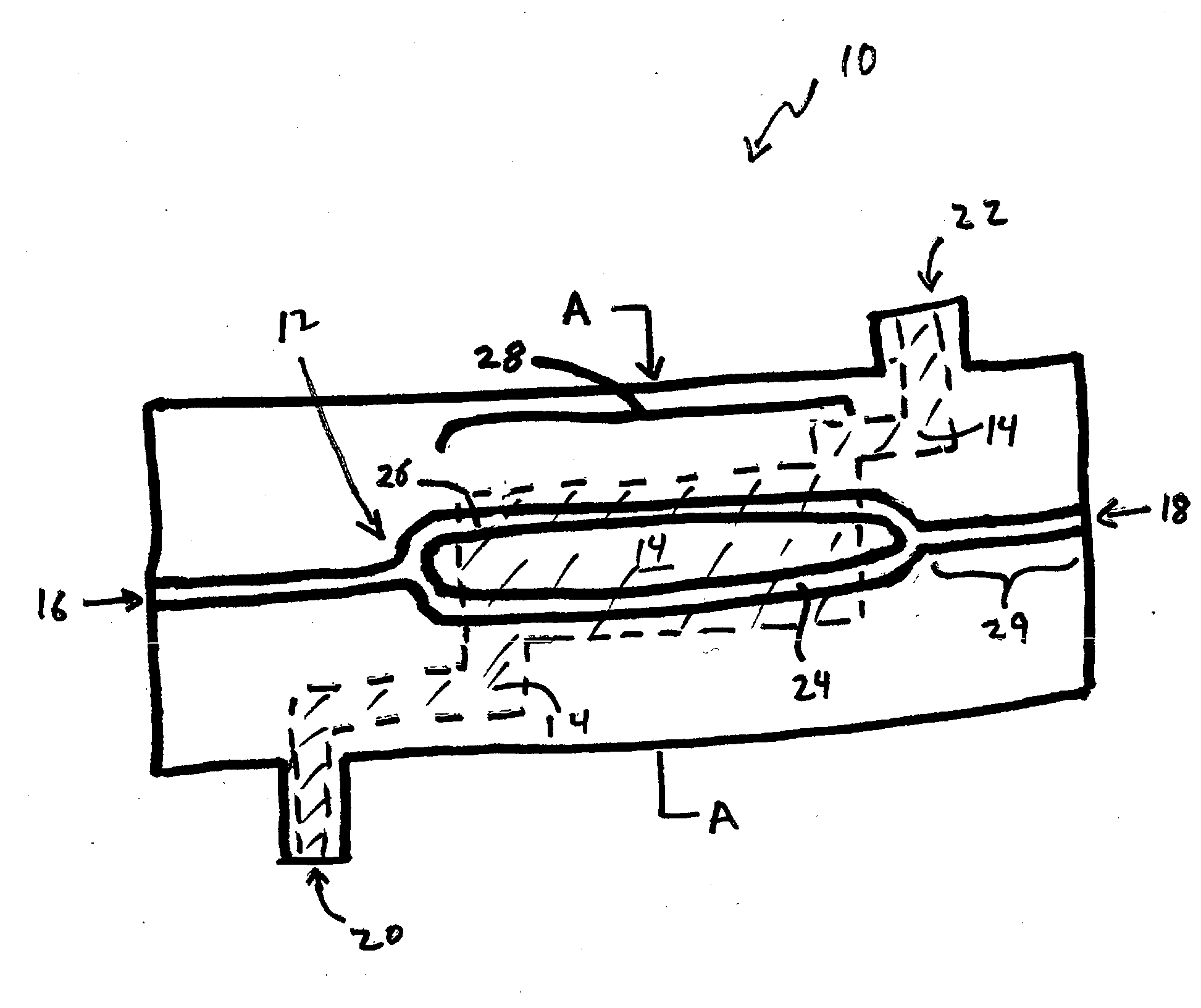
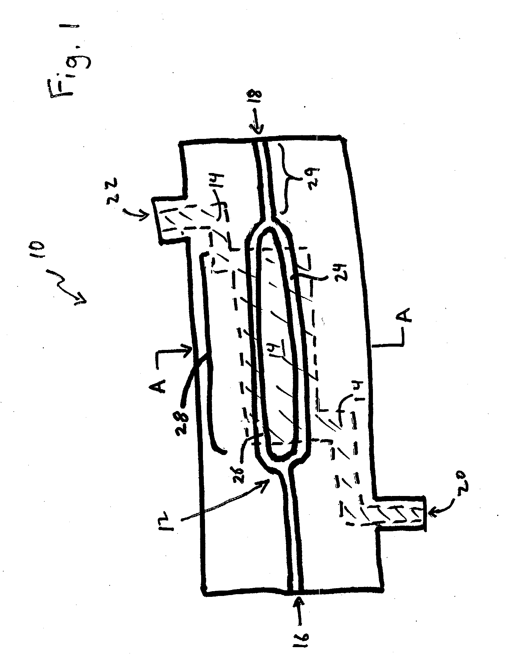
[0018] FIG. 1 is a top view of an electro-optical modulator 10. The electro-optical modulator 10 includes an optical waveguide 12 and a control waveguide 14. The optical waveguide 12 includes input and output terminals 16, 18 and an internal Mach-Zehnder interferometer. The Mach-Zehnder interferometer includes two arms 24, 26, i.e., two separate optical waveguides. The control waveguide 14 includes input and output terminals 20, 22 and a channel portion that passes through the interior of the electro-optical modulator 10. The input and output terminals 20, 22 of the control waveguide 14 connect to an external driver for control waves, i.e., microwaves, millimeter waves, or submillimeter waves, and to an anti-reflection termination, respectively (both not shown).

[0019] Herein, microwaves, millimeter waves, and submillimeter waves have wavelengths in the approximate ranges of (1 cm, 100 cm], (0.1 cm, 1.0 cm], and [0.01 cm, 0.1 cm], respectively.

[0020] The electro-optical modulator 10 ...


PUM

PropertyMeasurementUnit
refractive indexaaaaaaaaaa
wavelengthaaaaaaaaaa
wave wavelengthsaaaaaaaaaa

Abstract

An electro-optical modulator includes an optical waveguide for carrying an optical carrier wave and a control waveguide for carrying a control wave. The optical waveguide includes a cladding layer and a core. The two waveguides are collinear and overlap in an interaction region so that the refractive index of the optical waveguide responds to electric fields generated by the control wave in the interaction region. The refractive index of the cladding layer at the control wave's wavelength is higher than the refractive index of the core at the optical carrier wave's wavelength.

Description

[0001] 1. Field of the Invention[0002] The inventions relate generally to optical telecommunications and, more particularly, to electro-optical modulators.[0003] 2. Discussion of the Related Art[0004] One goal of telecommunications research is to increase transmission rates for digital data. Presently, optical transmitters transmit digital data at rates that are below desired values. The transmission rate of an optical transmitter is, in part, limited by the frequency at which a modulator is able to encode data onto a continuous optical carrier wave.[0005] Typically, modulators amplitude-encode data onto the optical carrier wave using microwave or millimeter control waves. The control waves electro-optically modulate refractive indexes in optical waveguides of the modulator. The optical waveguides form arms of an optical interferometer. By modulating refractive indexes, the control waves modulate propagation times in the arms of the interferometer and thus, intensity distributions p...

Claims


Application Information

Patent Timeline
Patent Type & Authority Applications(United States)
IPC IPC(8): G02B6/10G02B6/12G02B6/122G02B6/26
CPCG02B6/10G02B6/12004G02B6/1221G02B6/26G02B2006/12197G02B2006/12061G02B2006/12069G02B2006/12097G02B2006/12176G02B2006/12038
Inventor ERBEN, CHRISTOPH GEORGGILL, DOUGLAS M.KATZ, HOWARD EDANLEE, MARK
Owner WSOU INVESTMENTS LLC
Features
  • R&D
  • Intellectual Property
  • Life Sciences
  • Materials
  • Tech Scout
  • Unparalleled Data Quality
  • Higher Quality Content
  • 60% Fewer Hallucinations
Learn More