Mixed working fluid power system with incremental vapor generation

Inactive Publication Date: 2003-09-11
MIDWEST RES INST
View PDF5 Cites 55 Cited by
  • Summary
  • Abstract
  • Description
  • Claims
  • Application Information

AI Technical Summary

Benefits of technology

0008] A power generating system according to the present invention may comprise a heat source and an incremental vapor generator system operatively associated with the heat source. The incremental vapor generator system includes a first heating section and a second heating section. The first heating section receives a mixed working fluid and generates a first heated working fluid stream comprising a vapor portion and a liquid portion. The second heating s

Problems solved by technology

While power plants operating in accordance with the Rankine cycle are well-known and widely used, certain characteristics of the Rankine cycle impose fundamental limitations on the thermodynamic efficiency of t

Method used


Image

  • Mixed working fluid power system with incremental vapor generation
  • Mixed working fluid power system with incremental vapor generation
  • Mixed working fluid power system with incremental vapor generation

Examples


Embodiment Construction

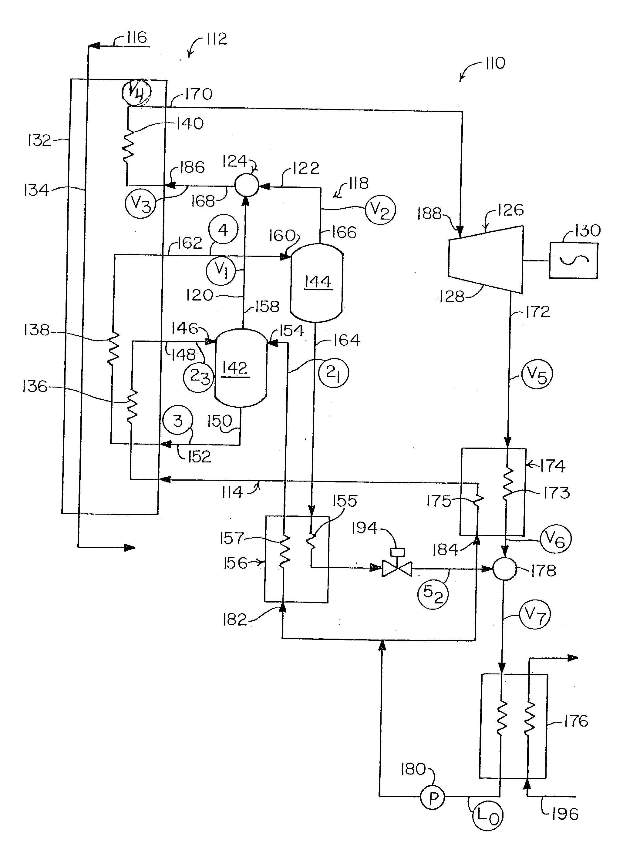
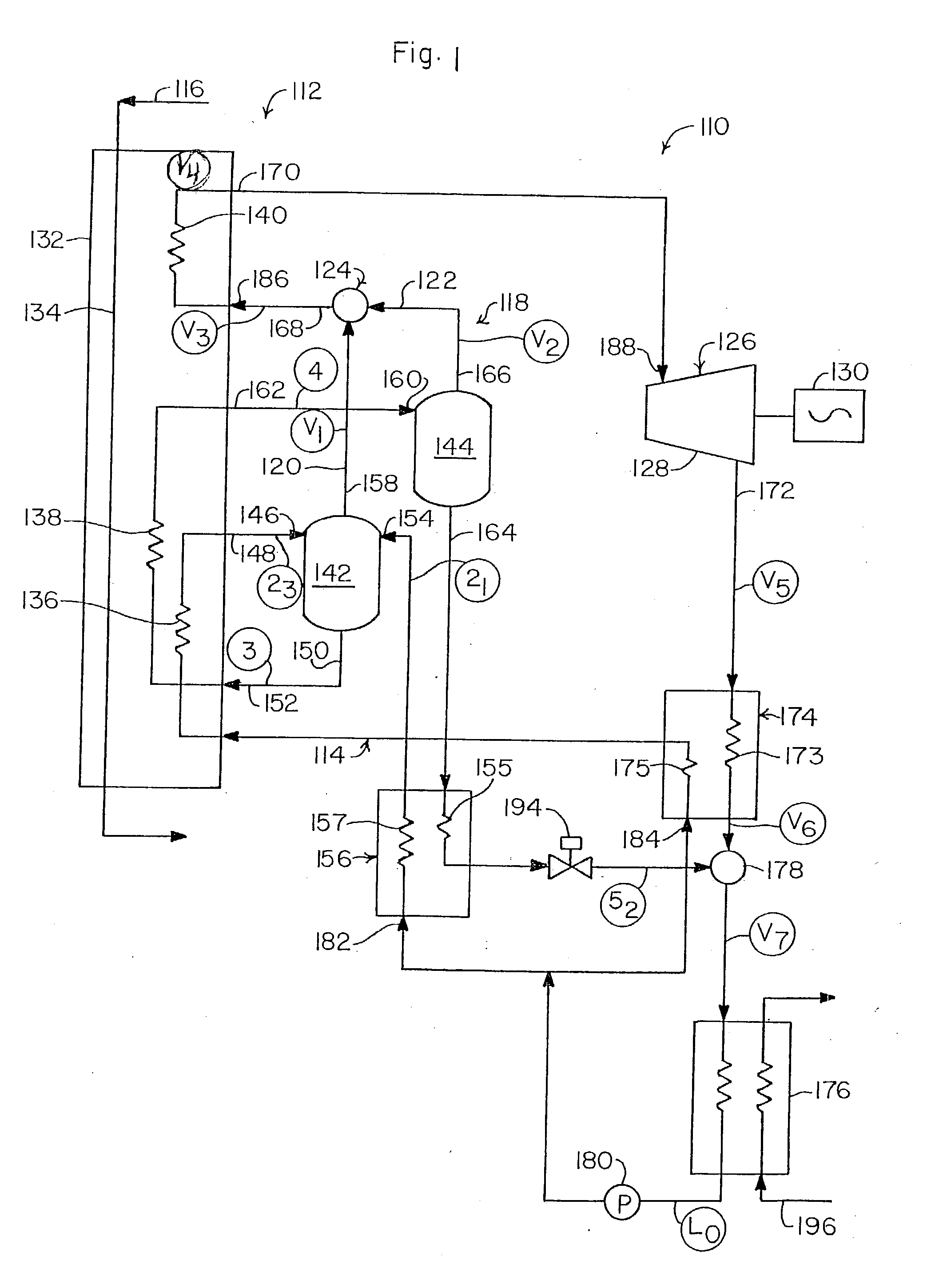
[0017] A power generating system 110 according to one embodiment of the present invention is shown in FIG. 1 and may comprise an incremental vapor generator system 112 for vaporizing a mixed working fluid 114. The incremental vapor generator system 112 incrementally vaporizes the mixed working fluid 114 with heat energy extracted from a heat source, such as, for example, geothermal brine 116. Alternatively, and as will be described in greater detail below, the present invention may be utilized with other types of heat sources and / or other types of heating fluids.

[0018] In the embodiment shown in FIG. 1, the incremental vapor generator system 112 comprises a parallel flow incremental vapor generation system 118 in which the mixed working fluid 114 is incrementally vaporized to form a first vapor portion 120 and a second vapor portion 122. The first and second vapor portions 120 and 122 thereafter may be combined in a vapor mixer 124 before being directed to an energy conversion syste...


PUM


Abstract

A power generating system (110) comprising a heat source (116) and an incremental vapor generator system (112) operatively associated with the heat source (116). The incremental vapor generator system (112) includes a first heating section (136) and a second heating section (138). The first heating section (136) receives a mixed working fluid (114) and generates a first heated working fluid stream comprising a vapor portion (120) and a liquid portion. The second heating section (138) is operatively associated with the first heating section (136) and receives the liquid portion from the first heated working fluid stream. The second heating section (138) generates a second heated working fluid stream comprising a vapor portion (122). An energy conversion device (126) operatively associated with the incremental vapor generator system (112) converts into useful work heat energy contained in the vapor portions (120, 122) of the first and second heated working fluid streams.

Description

[0002] This invention relates to power generation systems in general and more specifically to power generation systems utilizing mixed working fluids.[0003] Power generation systems or power plants are well-known in the art and are widely used to generate electricity. Most such power generation systems generate electricity from heat energy derived from burning fossil fuels (e.g., coal or natural gas) and are referred to herein as thermal power plants. In addition to using heat energy derived from burning fossil fuels, thermal power plants can also be used with a wide variety of other heat sources, such as solar, geothermal, and nuclear sources.[0004] Traditionally, thermal power plants have operated in accordance with the well-known Rankine thermodynamic cycle. In the Rankine cycle, a so-called "pure" working fluid, such as water, is heated to produce vapor or steam. The steam is then expanded, typically through a turbine, in order to convert heat energy contained therein into mecha...

Claims


Application Information

Patent Timeline
IPC IPC(8): F01K25/06
CPCF01K25/065
Inventor BHARATHAN, DESIKANHASSANI, VAHAB
Owner MIDWEST RES INST
Why Eureka
Try Eureka