Garbage carbonization reacting system

A chemical reaction and garbage charcoal technology, applied in the field of garbage carbonization reaction system, can solve the problems of high operating cost, odor pollution, high processing cost, etc., and achieve the effect of high degree of automation, economical operating cost and low classification requirements

Active Publication Date: 2015-01-07
NANTONG QIANGSHENG SAFETY PROTECTION TECHNOLOGY CO LTD
View PDF5 Cites 24 Cited by
  • Summary
  • Abstract
  • Description
  • Claims
  • Application Information

AI Technical Summary

Problems solved by technology

[0014] 2. Combustion residue still needs landfill
Because the residue contains heavy metals and other harmful substances, the treatment technology requires high requirements, the treatment equipment is complex, and the treatment cost is high. If some incineration plants cannot completely detoxify the residue or do not treat it thoroughly, this will cause damage to the soil and groundwater. serious pollution
[0016] 3. High investment with little economic return
[0021] Garbage sorting and composting is to use the ability of microorganisms to decompose the organic matter in the garbage. After composting, it becomes crop fertilizer, and the inorganic metal objects, glass, bricks, etc. are buried, and rubber and plastics are used. Recycling; but the amount of composting of domestic waste is large, and the content of nitrogen and phosphorus is low. Long-term use will easily cause soil compaction and groundwater quality to deteriorate. At the same time, it also has the following outstanding problems: 1. Odor pollution; 2. High operating costs; 3. The technology is immature; 4. The factory management is poor, so the waste sorting and composting technology is not yet mature
However, this utility model is only limited to the use of construction waste and coal powder to make finished coal, and cannot be applied to the reaction coal production of domestic waste.

Method used


Image

  • Garbage carbonization reacting system
  • Garbage carbonization reacting system
  • Garbage carbonization reacting system

Examples


Embodiment Construction

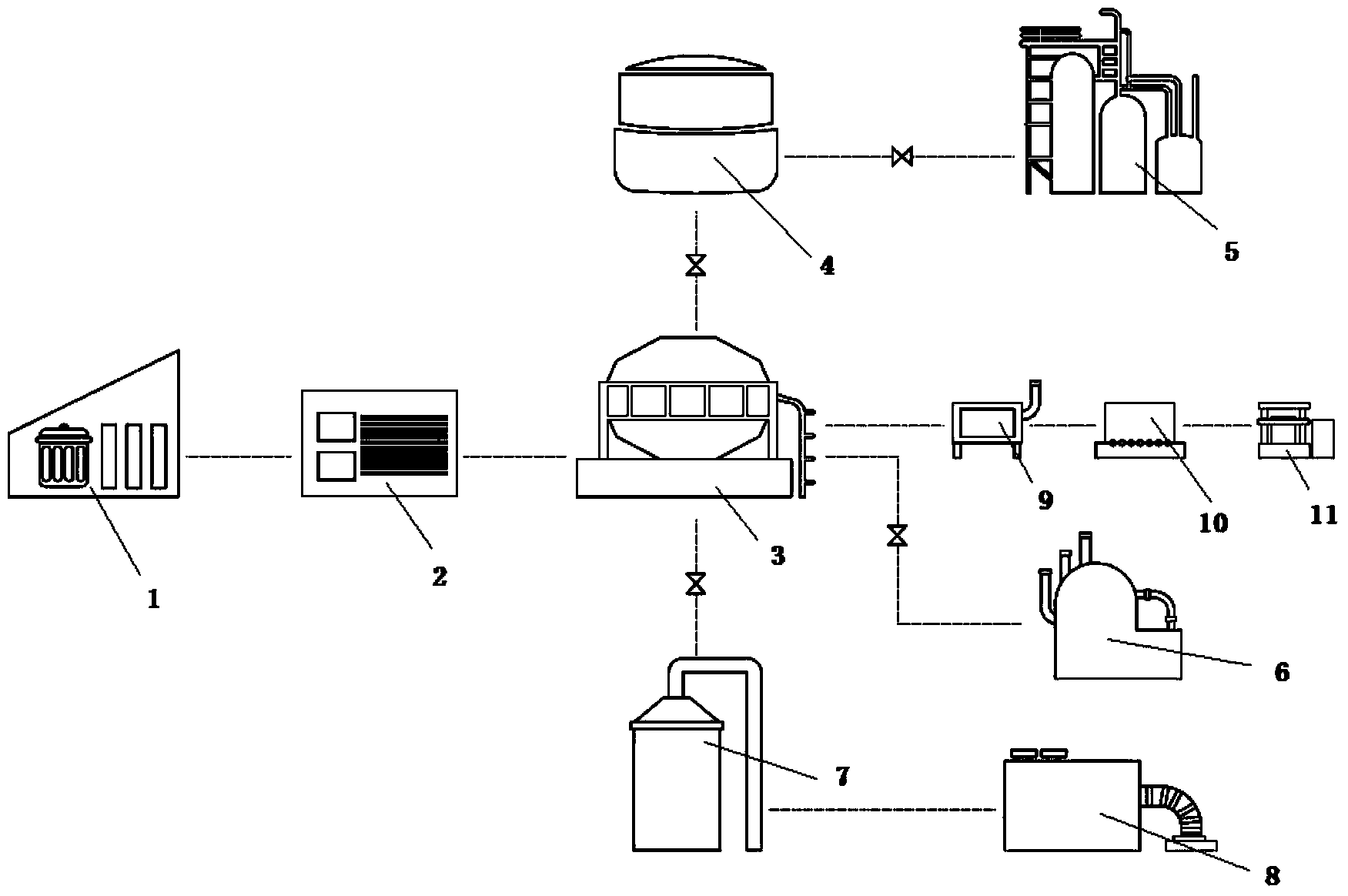
[0112] The present invention will be described in detail below in conjunction with specific embodiments. The following examples will help those skilled in the art to further understand the present invention, but do not limit the present invention in any form. It should be noted that those skilled in the art can make several modifications and improvements without departing from the concept of the present invention. These all belong to the protection scope of the present invention.

[0113] In this embodiment, the garbage carbonization reaction system provided by the present invention includes a reactor 3, a reaction tank 2, a steam generator 6 and a control device;

[0114] Wherein, the control device is connected to the reactor 3, and the steam generator 6 is connected to the reactor 3, and the steam generator 6 is used to provide steam to the reactor 3; the control device is used to control the reactor 3 Changes in pressure and temperature and reaction time.

[0115] The r...


PUM


Abstract

The invention provides a garbage carbonization reacting system. The system comprises a reaction still, a reaction tank, a vapor generator and a control device, wherein the vapor generator is connected with the reaction still, and the vapor generator is used for supplying vapor to the reaction still; the reaction tank is used for placing garbage. When a reaction is carried out, the reaction tank is pushed into the reaction still to react to generate a carbonization mixture; after the reaction is completed, the reaction tank is pulled out of the reaction still. The reaction still comprises a still body and a still cover, wherein the still body is connected with the still cover in a sealing manner; the control device is connected with the reaction still, and the control device is used for controlling the change of the pressure and the temperature in the reaction still and the reaction time; a first guide rail which extends in the length direction of the still body is arranged in the still body. The system disclosed by the invention has the advantages that the structural scheme is reasonable, the device is advanced, the degree of automation is high, the investment cost of equipment is low, the occupation area of a required plant is small, and burning value of prepared biomass fuel is high, and the discharge is low.

Description

technical field [0001] The invention relates to the technical field of domestic waste treatment, in particular to a waste carbonization reaction system. Background technique [0002] According to data, the average annual growth rate of domestic waste in my country is 8% to 10%. In 2013, the urban domestic waste reached 260 million tons, and the annual domestic waste in rural areas was nearly 100 million tons. major issues of governance. In this regard, the national and local governments at all levels attach great importance to it. In recent years, our country has introduced a series of new policies and new plans to make a comprehensive policy and practical explanation of the waste disposal problem. Especially during the "Twelfth Five-Year Plan" period, the state has The formulation of major plans in the field of environmental protection and waste management provides important development opportunities for my country's domestic waste treatment projects. At the same time, the ...

Claims


Application Information

Patent Timeline
Patent Type & Authority Applications(China)
IPC IPC(8): C10B53/00C10B49/02C10B57/10C10L5/46B09B3/00B09B5/00
CPCY02E50/30Y02E50/10C10B53/00C10L5/46B09B3/00C10B49/02C10B57/10
Inventor 沙嫣沙晓林
Owner NANTONG QIANGSHENG SAFETY PROTECTION TECHNOLOGY CO LTD
Why Eureka
Try Eureka