Fiber optic sensor

a fiber optic sensor and fiber optic technology, applied in the field of optical sensors, can solve the problems of difficult manufacture, high cost, and measurement of light wavelengths, and achieve the effect of improving the accuracy of measurement results

Inactive Publication Date: 2003-09-11
HONEYWELL INT INC
View PDF8 Cites 45 Cited by
  • Summary
  • Abstract
  • Description
  • Claims
  • Application Information

AI Technical Summary

Benefits of technology

0009] According to various exemplary embodiments, a technique for sensing an environmental effect upon a sensing element suitably includes exposing the sensing element into the environmental effect, producing a light signal in the sensing element, modulating the light signal with a modulation "drive" signal, and determining a path length of the light signal from the resulting modulated signal on a sensing optical detector, as a function of the modulation drive signal. According to further exemplary embodiments, a fiber optic sensor suitably includes a light source producin

Problems solved by technology

Such sensors have exhibited a number of marked disadvantages, however, in that they are typically expensive, difficult to manufacture, and require measurements of light wav

Method used


Image

  • Fiber optic sensor
  • Fiber optic sensor
  • Fiber optic sensor

Examples


Embodiment Construction

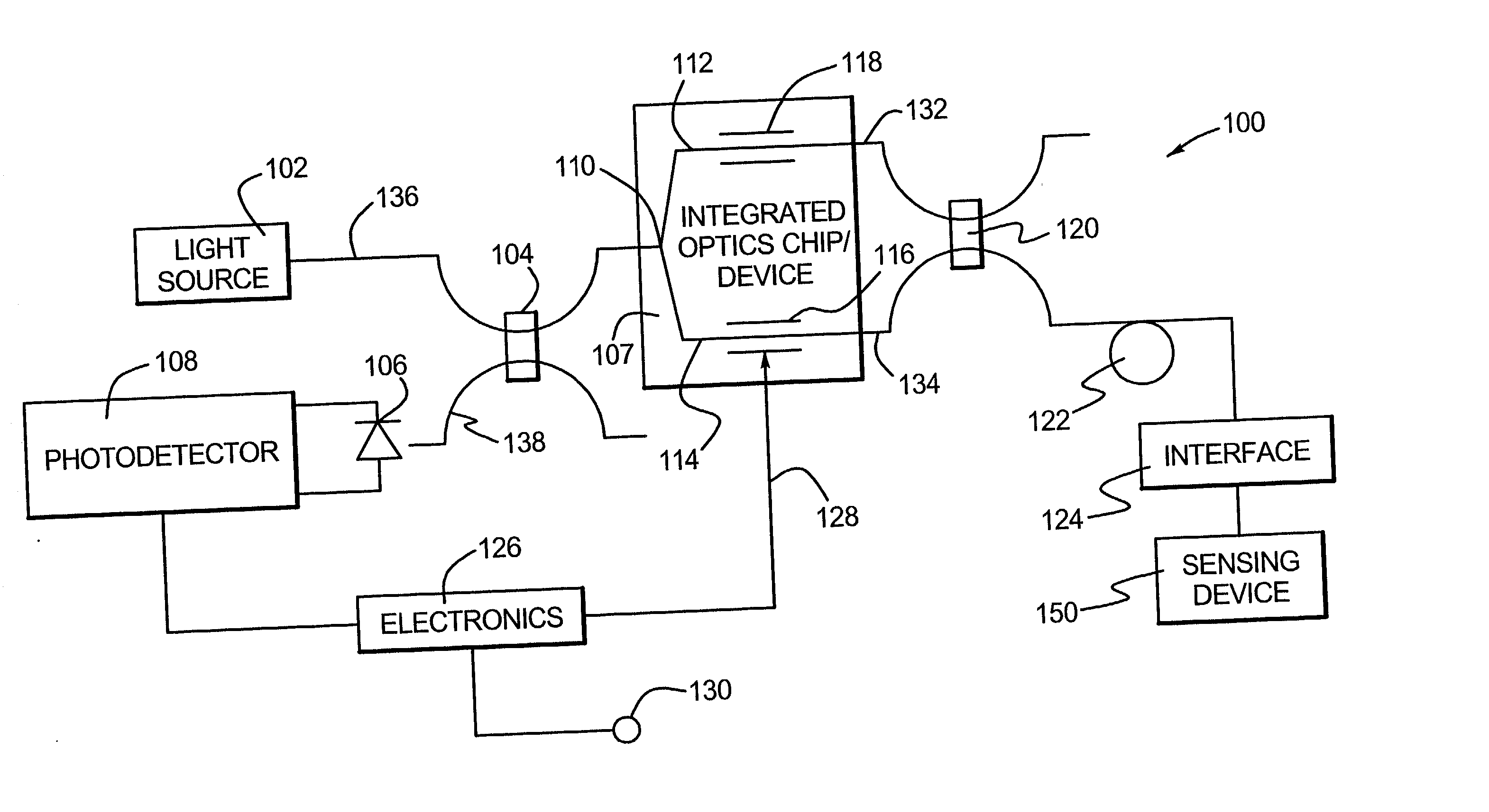
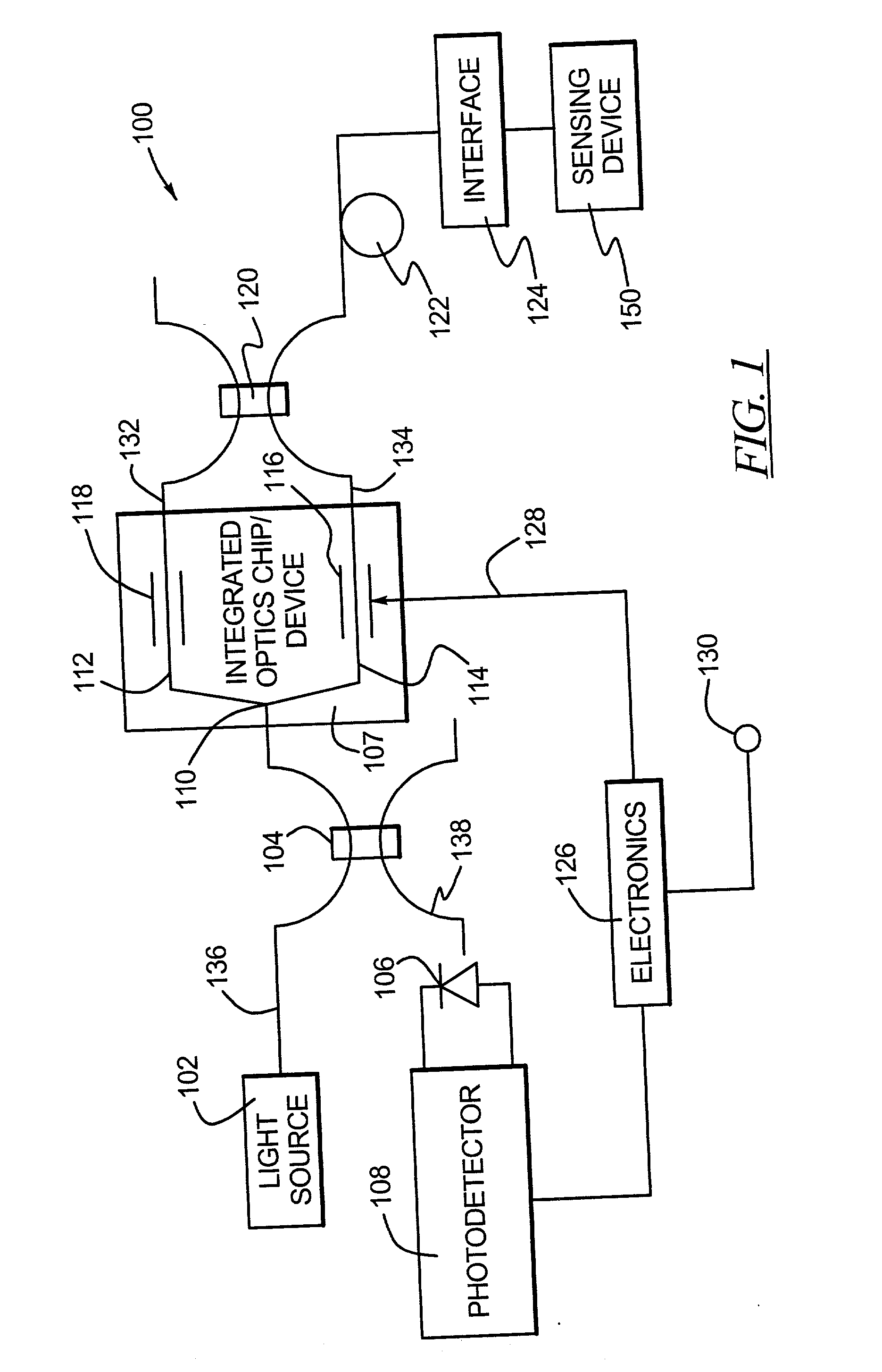
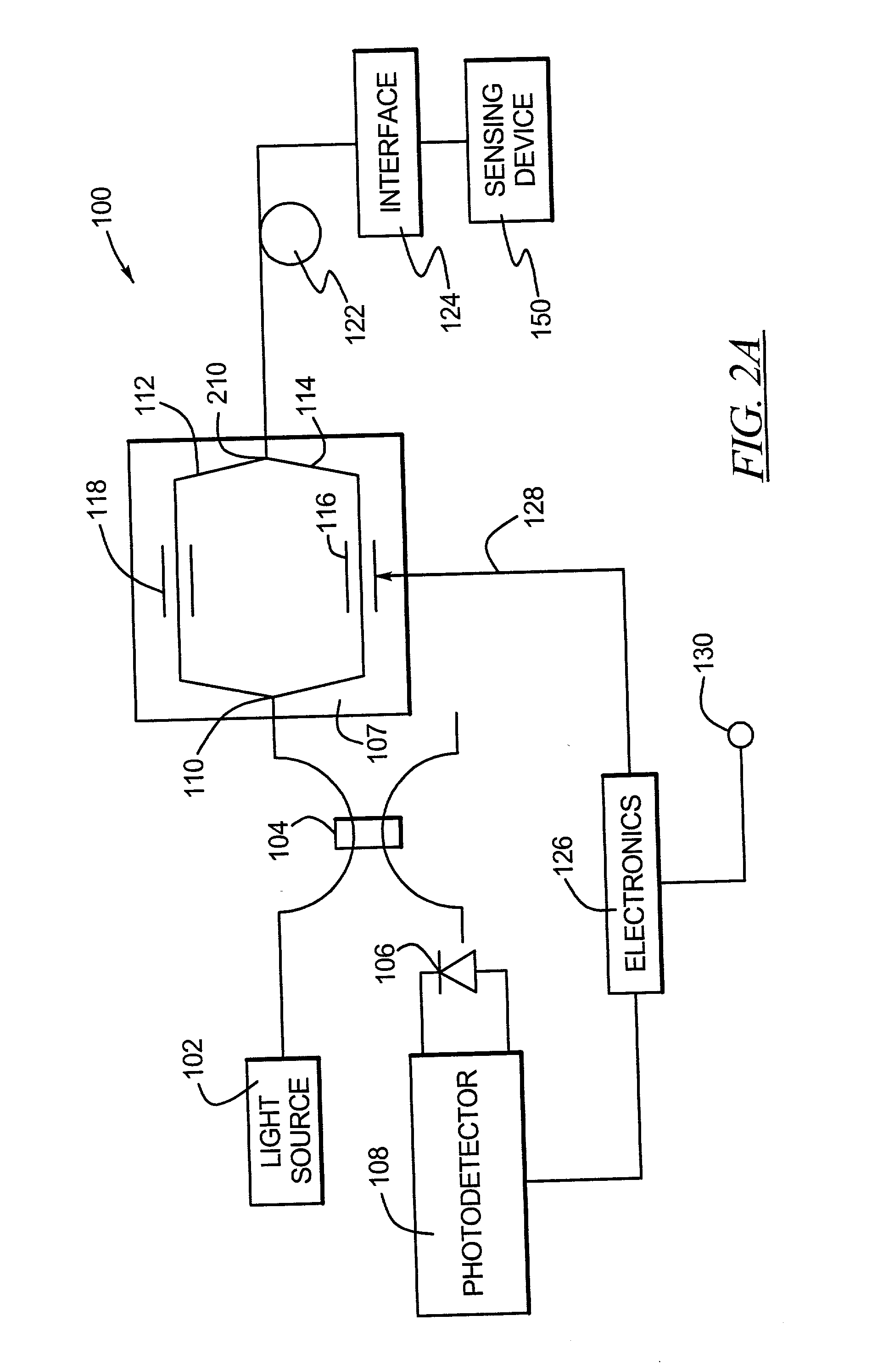
[0009] According to various exemplary embodiments, a technique for sensing an environmental effect upon a sensing element suitably includes exposing the sensing element into the environmental effect, producing a light signal in the sensing element, modulating the light signal with a modulation "drive" signal, and determining a path length of the light signal from the resulting modulated signal on a sensing optical detector, as a function of the modulation drive signal. According to further exemplary embodiments, a fiber optic sensor suitably includes a light source producing a light, a sensing element optically coupled to the light source such that the light propagates through the sensing element, a detector optically coupled to the sensing element. The detector is configured to detect the intensity of the light propagating in the sensing element and to produce a detector output indicative of the intensity; and the electronics receive the detector output and produce a modulation sig...


PUM


Abstract

A method is provided for sensing an environmental effect upon a sensing element and includes exposing the sensing element into the environmental effect, producing a light signal in the sensing element, modulating the light signal with a modulation signal, and determining a path length of the light signal as a function of the modulation signal. A fiber optic sensor is provided that includes a light source producing a light, a sensing element optically coupled to the light source such that the light propagates through the sensing element, a detector optically coupled to the sensing element. The detector detects light intensity propagating in the sensing element. An electronics processor receives the detector output and produces a modulation signal for the light. The processor further produces an output signal indicative of the environmental effect as a function of the modulation signal.

Description

[0001] 1. Technical Field[0002] The invention relates generally to optical sensors, and particularly to interferometric sensors for determining environmental effects.[0003] 2. Description of the Related Art[0004] As fiber optics become more prevalent, various types of optical sensors have become increasingly common. Indeed, various types of sensors detect fiber lengths, locations of breaks / cracks / inconsistencies in optical fibers, temperature, pressure, fiber expansion, attributes of chemical species, and the like.[0005] Optical fibers may be subjected to various external effects that produce geometric (e.g., size, shape) and / or optic (e.g., refractive index, mode conversion) changes to the fiber depending upon the nature and the magnitude of the perturbation. While these effects are often considered to be parasitic (i.e., noise-causing) in communications applications, the fibers response to external influence may be increased in sensing applications so that the resulting change in ...

Claims


Application Information

Patent Timeline
IPC IPC(8): G01B11/16G01L1/24G01C19/64G01C19/72G01D5/26G01D5/353G01K11/12G01S7/481G01S17/32G01S17/36G01S17/88
CPCG01B11/16G01C19/64G01C19/72G01D5/268G01S17/88G01S7/4811G01S7/4818G01S17/36G01N21/431
Inventor LANGE, CHARLESSANDERS, STEVEANG, DICKSTRANDJORD, LEE K.
Owner HONEYWELL INT INC
Why Eureka
Try Eureka