Planar magnetron targets having target material affixed to non-planar backing plates

a technology of non-planar backing plates and magnetron, which is applied in the direction of electrolysis components, vacuum evaporation coatings, coatings, etc., can solve the problems of unrecoverable manufacturing occurrence, uneven surface of target eroded, and thermal expansion of backing plates 102

Inactive Publication Date: 2003-09-25
LYNN DAVID MARK +1
View PDF3 Cites 34 Cited by
  • Summary
  • Abstract
  • Description
  • Claims
  • Application Information

AI Technical Summary

Problems solved by technology

One of the problems with the targets used in planar magnetrons is that the surface of the target erodes unevenly.
Another problem with the targets used in planar magnetrons is that the backing plate 102 may have thermal expansion characteristics which are dissimilar to those of the target material.
Such an event may constitute an unrecoverable manufacturing occurrence, which would require either the discarding or reworking of the substrate.

Method used


Image

  • Planar magnetron targets having target material affixed to non-planar backing plates
  • Planar magnetron targets having target material affixed to non-planar backing plates
  • Planar magnetron targets having target material affixed to non-planar backing plates

Examples


first embodiment

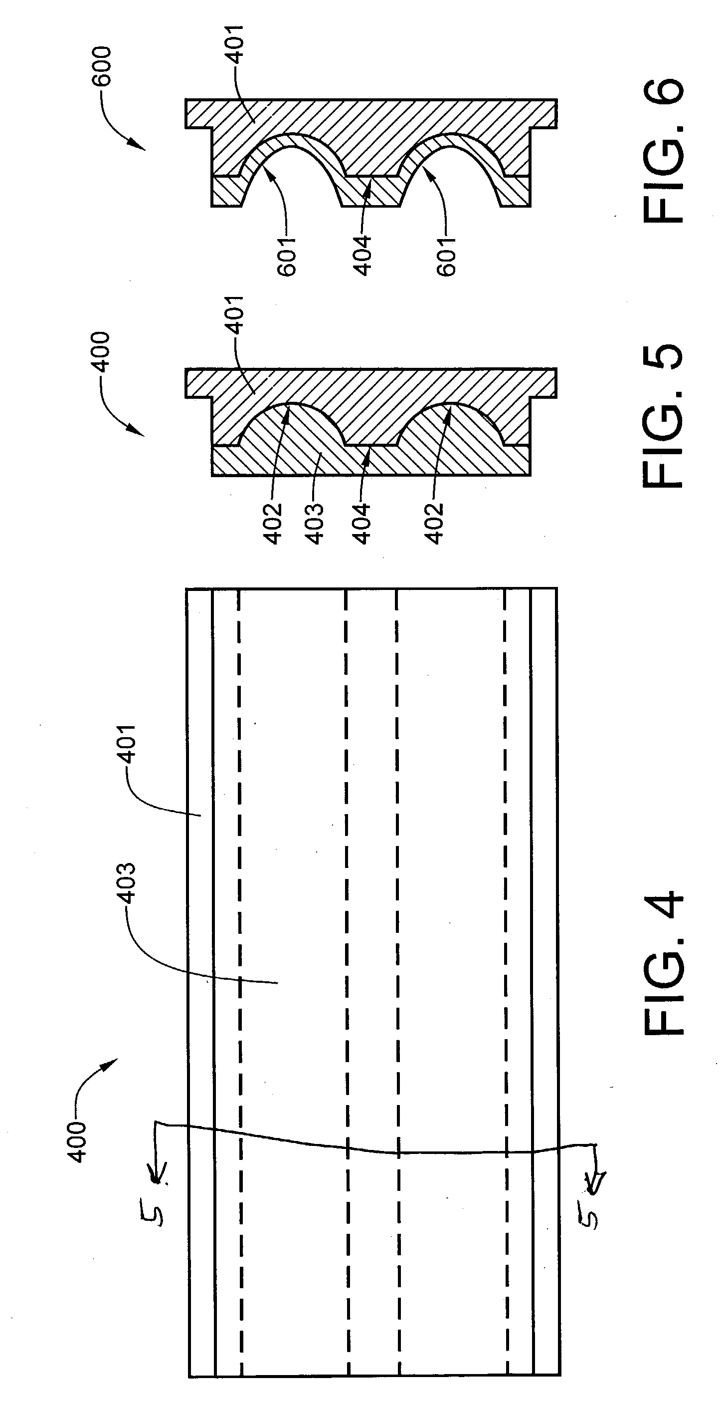
[0026] Referring now to FIGS. 4 and 5, a first a first embodiment improved planar magnetron target 400 includes a backing plate 401 which incorporates a groove 402 of substantially semicircular cross section in each region where the plasma is magnetically confined. The target material 403 is applied such that the grooves are completely filled therewith. This design affords a much greater effective depth of target material, as the erosion of the target material in the confined plasma regions of the target material may continue well below the face 404 of the backing plate.

[0027] After the target of FIG. 5 is used to the point where it must be discarded, it may assume the appearance of the used target 600 of FIG. 6.

[0028] Referring now to FIGS. 7 and 8, a second embodiment improved planar magnetron target 700 incorporates the grooved backing plate 401 of the first embodiment target 400, but add the additional feature of a target material layer 701 that is formed in relief. The shaped s...

fifth embodiment

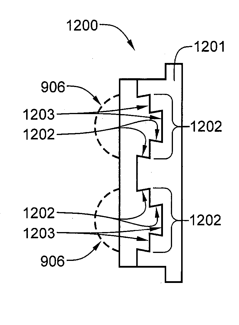
[0032] Referring now to FIG. 12, the fifth embodiment planar magnetron target 1100 includes a backing plate 1201 having primary grooves 1202 formed by steps 1203. The front of each step 1202 is undercut, which assists in the retention of the target material.

[0033] The backing plates of the various embodiments of the improved planar magnetron targets described heretofore may be manufactured from any one of a number of conventional metals currently in use, such as aluminum, aluminum alloys, steel, stainless steel, and copper. The target material may include any of the target materials presently used in the sputtering industry.


PUM

PropertyMeasurementUnit
erosion depthaaaaaaaaaa
adhesionaaaaaaaaaa
electric fieldaaaaaaaaaa

Abstract

Planar magnetron targets are disclosed which include a backing plate which is grooved in the regions where erosion of the target material mainly occurs, thereby permitting greater erosion depth of the target material. The life of the target material may be further extended by employing an in-relief upper surface for the target material. The in-relief surface may be prepared by a number of well-known techniques, which include casting and computer-controlled plasma spray. The target material may be either sprayed on or bonded to the backing plate. For a preferred embodiment of the invention, the backing plate is grooved to create undercut ledges which retain the target material on the backing plate, even if adhesion between the surfaces of the target material and the backing plate material fails as the result of thermal cycling.

Description

[0001] This application has a priority date based on Provisional Patent Application No. 60 / 343,078, filed Dec. 21, 2001.[0002] This invention relates generally to equipment employed for the coating of substrate articles by magnetron sputtering and, more specifically, to the design of planar targets, as well as methods and apparatus for affixing such targets to a target backing plate.DESCRIPTION OF THE PRIOR ART[0003] Sputtering is the physical ejection of material from a target as a result of ion bombardment of the target. The ions are usually created by collisions between gas atoms and electrons in a glow discharge. The ions are accelerated into the target cathode by an electric field. A substrate is placed in a suitable location so that it intercepts a portion of the ejected atoms. Thus, a coating is deposited on the surface of the substrate. For at least several decades, sputtering has been the dominant process for the deposition of thin coatings on large-surface-area substrates,...

Claims


Application Information

Patent Timeline
Patent Type & Authority Applications(United States)
IPC IPC(8): C23C14/34H01J37/34
CPCC23C14/3407H01J37/3482H01J37/3435
Inventor LYNN, DAVID MARKCLARKSON, MELVIN MARION
Owner LYNN DAVID MARK
Why Eureka
Try Eureka