Probe card carrier and method of carrying probe card

a technology of probe card and probe card body, which is applied in the direction of individual semiconductor device testing, semiconductor/solid-state device testing/measurement, instruments, etc., can solve the problems of low operation efficiency of the probe card replacement device, large footprint of the probe device in a clean room, and higher equipment cost, so as to increase the size and weight of the probe card, and increase the effect of size and weigh

Inactive Publication Date: 2003-09-25
TOKYO ELECTRON LTD
View PDF8 Cites 22 Cited by
  • Summary
  • Abstract
  • Description
  • Claims
  • Application Information

AI Technical Summary

Benefits of technology

0007] As objects-to-be-inspected such as wafers has have become large-sized and highly integrated, probe cards have been increased in size and weight. To cope with the increase of the size and weight of the probe card, the probe card replacing device is also increased in size, thus the probe card replacing device occupies a wider space in the probe device. Thus, a problem was also grasped that the footprint of the probe device in a clean room is larger and the equipment cost is higher.

Problems solved by technology

Thus, a problem was grasped that the operating efficiency of the probe card replacing device is low.
Thus, a problem was also grasped that the footprint of the probe device in a clean room is larger and the equipment cost is higher.
A problem was also grasped that a probe card is large-sized and as heavy as 20 kg, making it hard for an operator to carry the probe card about.

Method used


Image

  • Probe card carrier and method of carrying probe card
  • Probe card carrier and method of carrying probe card
  • Probe card carrier and method of carrying probe card

Examples


Embodiment Construction

[0032] The accompanying drawings, which are incorporated in and constitute a part of the specification, illustrate presently preferred embodiments of the invention, and together with the general description given above and the detailed description of the preferred embodiments given below, serve to explain the principles of the invention.

[0033] The present invention will be described on the basis of the embodiments shown in FIGS. 1A to 6B.

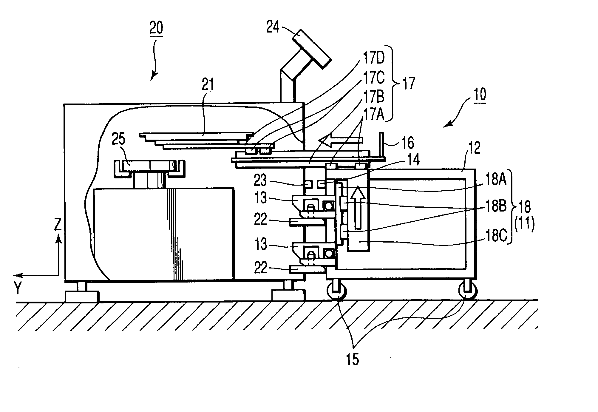
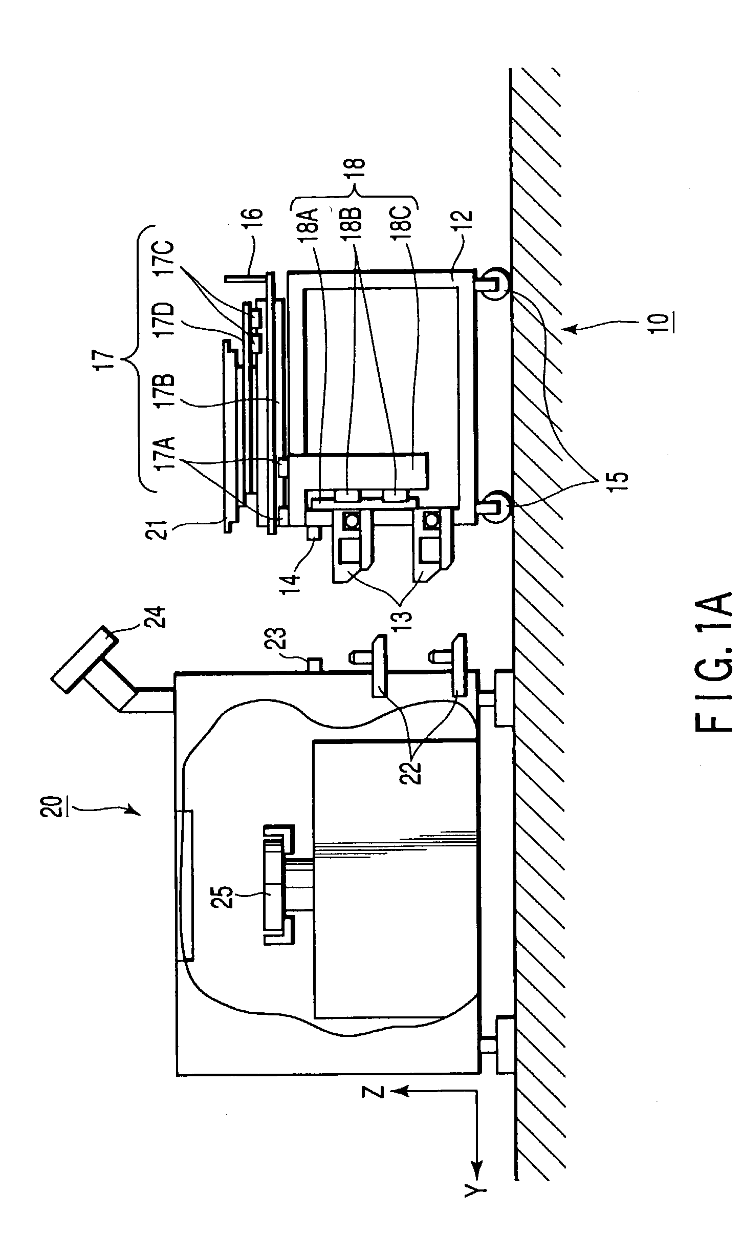
[0034] FIGS. 1A and 1B show a probe card conveyor 10 according to one embodiment of the present invention. The probe card conveyor 10 conveys a probe card 21 (e.g., outside diameter: 600 mm, weight: 20 kg) to a probe device 20. The probe card conveyor 10 comprises a body 12, a plurality of coupling mechanisms 13 provided on that side of the body which is opposed to the probe device, and a battery (not shown) for driving the probe card conveyor 10. The coupling mechanisms 13 may be four in number, for example, and preferably, should be three. The pro...


PUM


Abstract

A probe card conveyor 10 comprises a probe card conveyor 10, a body 12 provided with the probe card conveyor 10, and coupling mechanisms 13 provided in a plurality of positions on that side of the body 12 which is opposed to the probe device 20 and coupled individually to four coupled fittings 22 of the probe device 20. Further, the probe card conveyor 10 comprises a probe card mounting mechanism 17 for transferring a probe card 21 in the Y-direction and a lift mechanism 18 for raising and lowering the probe card mounting mechanism 17.

Description

[0001] This application is based upon and claims the benefit of priority from the prior Japanese Patent Application No. 2001-239742, filed Aug. 7, 2001, the entire contents of which are incorporated herein by reference.[0002] The present invention relates to a probe card conveyor and a probe card conveying method. More specifically, the invention relates to a probe card conveyor and a probe card conveying method capable of reducing the footprint (installation area) of a probe device. From another standpoint, moreover, the present invention relates to a probe card conveyor and a probe card conveying method capable of improving the safety of conveying operation for large-sized probe cards.[0003] A probe device is a device that is used to examine the electrical properties of an object-to-be-inspected (e.g., integrated circuit formed on a wafer, hereinafter referred to as "wafer"). Usually, the probe device comprises a main chuck, that can move in X-, Y-, Z-, and .theta.-directions, and...

Claims


Application Information

Patent Timeline
Patent Type & Authority Applications(United States)
IPC IPC(8): G01R31/26B23Q7/14G01R31/28H01L21/66H01L21/677
CPCB23Q7/1442G01R31/2887H01L21/67724H01L21/67778H01L21/67748H01L21/67763H01L21/67775H01L21/67736H01L22/00
Inventor SUZUKI, MASARU
Owner TOKYO ELECTRON LTD
Why Eureka
Try Eureka