
Method and apparatus for borehole sensing

a technology of borehole and sensing device, which is applied in the field of acoustic sensor configuration and methods, can solve the problem that the clamp does not address the problem of a stuck tool, and achieve the effect of effective and removable deployment or spooling, small profile, and improved reliability of the downhole sensor system

Active Publication Date: 2003-09-25
SCHLUMBERGER TECH CORP
View PDF6 Cites 70 Cited by
  • Summary
  • Abstract
  • Description
  • Claims
  • Application Information

AI Technical Summary

Benefits of technology

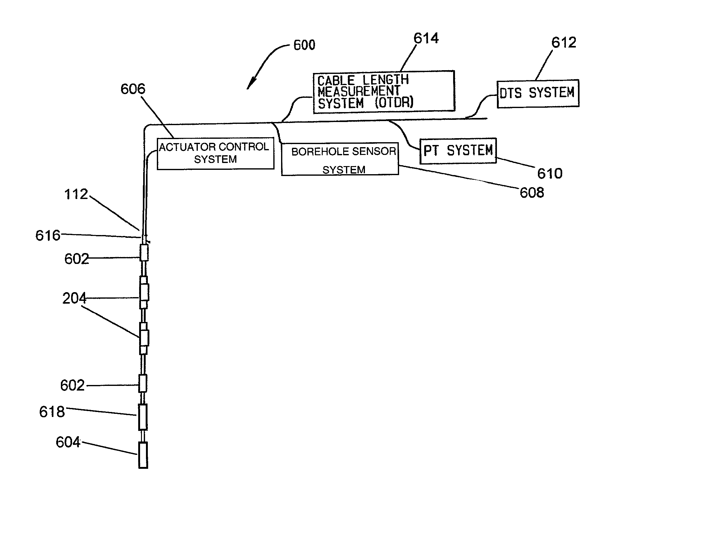
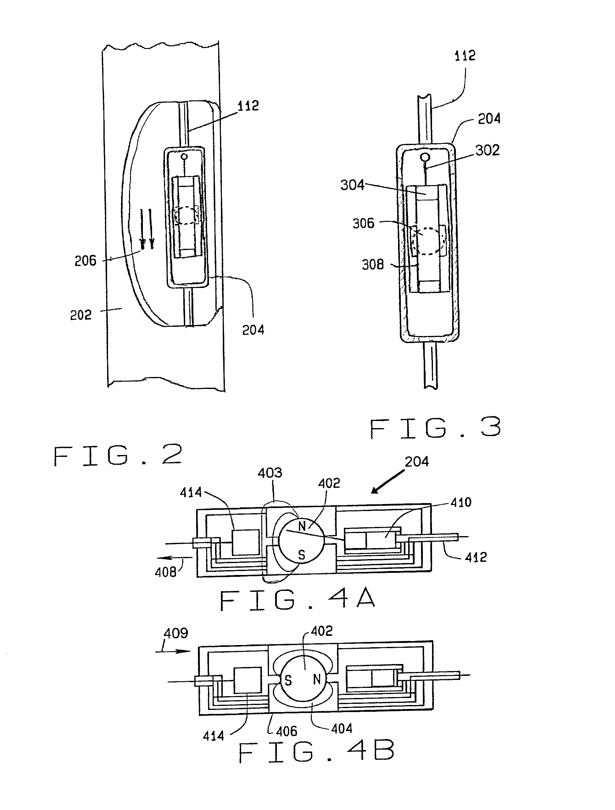
[0012] Also, as noted above, a magnet clamp is utilized to couple the shuttle to the borehole casing. The magnet clamp is more compact compared to typical mechanical surface force clamping devices utilized in the industry because it does not involve engagement of or movement of mechanical parts exposed outside shuttle. Also, the magnet clamp does not have to be positioned in a side passageway away from the primary flow passageway of the well and its use eliminates the need for mechanical anchoring arms thereby further reducing the shuttle size. One embodiment of the magnet clamp comprises a surface hydraulic actuator control system adapted to hydraulically control a downhole actuator for positioning of a magnet to engage or disengage the shuttle. Electrical actuator control systems can likewise be used. The magnetic clamp is a clear improvement over the typical mechanical surface force clamping because the seismic sensor system can be retracted and utilized in different boreholes. However, as indicated above the magnet clamp does not address the issue of a stuck tool.
[0013] Another embodiment can comprise a conveyance having a sensor section where the various sensors are attached and a weak point in the conveyance below the small outer diameter sensor section and where the larger outer diameter main electronics cartridges, weights or other larger components are attached to the conveyance below the weak point. This embodiment facilitates fishing a stuck tool and if necessary breaking away the upper portion of the conveyance at the weak point.
[0014] Another embodiment of the invention incorporates bow springs with the shuttle for facilitating coupling and decoupling of the sensor. The bow spring can be adapted to extend the shuttle away from the conveyance toward the borehole casing and retract the shuttle against the conveyance
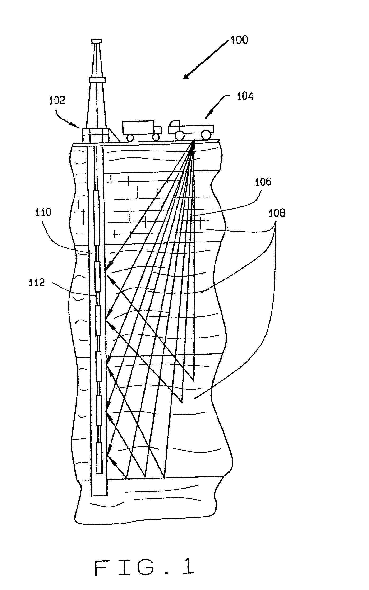
[0016] One embodiment of the present invention is an apparatus and method that utilizes the benefits of fiber optic communication and sensor systems combined with a plurality of shuttle devices attached along a coiled tubing, or a cable line, wire line, slickline, or other suitable downhole deployment means. The shuttle provides a housing for the sensors and each shuttle has a magnetic coupling clamp which enables the present invention to effectively and removably deploy or spool seismic sensor arrays downhole into a survey borehole for recording multi-level three-dimensional borehole seismic data. The borehole monitoring or deployment tool comprises a coiled tubing, or a cable line, wire line, slickline or other suitable conveyance for extending a plurality of shuttle devices containing fiber optic seismic sensors where the shuttle devices have a magnetic coupling clamp controllably operable to fixedly engage and acoustically couple the shuttle to the borehole casing. The magnetic clamp is further controllably operable to disengage and uncouple the shuttle from the borehole casing.
[0017] When the present invention utilizes fiber optic sensor systems, it benefits from many advantages offered by fiber optic systems. For example, fiber optic systems can operate passively and therefore downhole electronics and associated power from the surface to operate the downhole electronics are not required. The ability to eliminate downhole electronics improves reliability of the downhole sensor system particularly in higher temperature environments. The electronics necessary for operating the sensor arrays can be located at the surface and since the surface electronics can be relatively expensive, they can be shared with other wells and utilized for multiple downhole fiber optic sensor systems. Also, fiber optic technology allows for a smaller profile and lighter weight system. Still further, all of these capabilities are advantageous for acoustic and seismic imaging applications which require a large sensor array with high data transmission capabilities. In this regard, fiber optic sensors can also support multi-functional measurements through the fiber optic line. This feature has great advantage in wire line or cable line applications as well as production and formation monitoring sensor systems.

Problems solved by technology

However, as indicated above the magnet clamp does not address the issue of a stuck tool.

Method used


Image

  • Method and apparatus for borehole sensing
  • Method and apparatus for borehole sensing
  • Method and apparatus for borehole sensing

Examples


Embodiment Construction

[0032] The present invention provides an apparatus and method for removably deploying seismic sensor arrays down a borehole or wellbore for efficiently recording subsurface seismic data. The apparatus is designed such that a plurality of seismic sensors or seismic sensor arrays can be deployed down a wellbore by spooling down a plurality of seismic sensors attached to a wire line (cable line), slickline, coiled tubing or other suitable deployment mechanism. For purposes of this disclosure, when any one of the terms wire line, cable line, slickline or coiled tubing or conveyance is used it is understood that any of the above-referenced deployment means, or any other suitable equivalent means, may be used with the present invention without departing from the spirit and scope of the present invention. One embodiment of the apparatus is designed with a plurality of shuttle containers or simply shuttles, each shuttle containing a sensor array with the shuttles being attached along the wi...


PUM


Abstract

The present invention provides an apparatus and method for sensing subsurface data. One embodiment of the invention comprises a shuttle attached to a conveyance where the conveyance and shuttle are adapted to be spooled downhole into a borehole for sensing seismic data. The shuttle contains a sensor package that is preferably acoustically isolated in the shuttle. The sensor package includes a sensor array and a magnet clamp. A sensor section can contain several shuttles, each shuttle containing at least one sensor. In one embodiment, the sensor can be a fiber optic sensor. The magnet clamp is operable to controllably clamp and acoustically couple together the sensor package, the shuttle, and the adjacent structure which is typically the borehole casing. The magnet clamp is likewise operable to unclamp and uncouple the shuttle from the adjacent structure so as to be retracted uphole for subsequent use.

Description

BACKGROUND OF INVENTION[0001] (1) Field of Invention[0002] This invention is related to development of acoustic sensors configurations and methods for efficiently recording subsurface seismic data and more particularly to utilization of acoustic sensors for recording borehole seismic data.[0003] (2) Background Art[0004] Borehole seismic data can be utilized to refine surface seismic data prior to drilling production wellbores. Borehole seismic data can further be gathered on a continuing or recurrent basis to monitor subsurface formations and reservoirs during production of the well. The gathering of data on a continuing basis will assist in optimizing extraction of gas or oil deposits.[0005] Borehole seismic surveys are conducted by placing the receivers in the borehole and operating a seismic source at the surface to generate an acoustic wave. Typically the receivers are placed in a shuttle and deployed downhole for the duration of the survey and then removed. The amount of inform...

Claims


Application Information

Patent Timeline
Patent Type & Authority Applications(United States)
IPC IPC(8): G01V1/40
CPCG01V1/40
Inventor NUTT, LESYAMATE, TSUTOMUKAMATA, MASAHIRO
Owner SCHLUMBERGER TECH CORP
Learn More