Method of manufacturing a thrust plate, method of manufacturing a shaft for a hydrodynamic bearing, hydrodynamic bearing, spindle motor, and recording disk drive device

a technology of thrust plate and manufacturing method, which is applied in the direction of sliding contact bearing, record information storage, instruments, etc., can solve the problems of more difficult to reliably obtain a sufficient degree of precision in the perpendicular angle of the central axis relative to the surface planes of the thrust plate, etc., to enhance the bearing performance of dynamic pressure bearing, reliable and highly precise degree of run-out precision

Inactive Publication Date: 2003-10-02
SOODE NAGANO +1
View PDF15 Cites 11 Cited by
  • Summary
  • Abstract
  • Description
  • Claims
  • Application Information

AI Technical Summary

Benefits of technology

0016] It is an object of the present invention to provide a method of manufacturing a thrust plate used in a dynamic pressure bearing that employs a shaft in which the shaft body thereof is fitted into the thrust plate, the thrust plate having a reliable and highly precise degree of run-out precision (perpendicular angle) in the end surfaces thereof relative to a central axis thereof, which thus enhances the bearing performance of the dynamic pressure bearing.

Problems solved by technology

On the other hand, because the end portion of shaft body of the dynamic pressure bearing shaft disclosed in the aforementioned Japanese Published Patent Application 2000-134897 is press fit into and fixed to the central hole of the thrust plate, and the shaft body and the thrust plate are separate components, it will be more difficult to obtain a perpendicular angle between the thrust plate planes relative to the axial center line of the shaft body that it would be when the shaft is manufactured by cutting it from a unitary member and machining it.
In this situation, it is difficult to reliably obtain a sufficient degree of precision even when the inner and outer peripheral surfaces are finished, and thus it will be difficult to reliably obtain a sufficient degree of precision in the perpendicular angle of the central axis relative to the surface planes of the thrust plate.
In the coining step, however, the material that forms the blank intermediate will not flow in the radial directions in a uniform manner, and thus it will be easy to produce non-uniform surfaces.
Thus, the degree to which both end surfaces of the blank intermediate are parallel to each other will be poor, and there will be large fluctuations thereon.
In addition, the fluctuations will not sufficiently eliminated in the pressing step, with the result that the heights of products will differ.

Method used


Image

  • Method of manufacturing a thrust plate, method of manufacturing a shaft for a hydrodynamic bearing, hydrodynamic bearing, spindle motor, and recording disk drive device
  • Method of manufacturing a thrust plate, method of manufacturing a shaft for a hydrodynamic bearing, hydrodynamic bearing, spindle motor, and recording disk drive device
  • Method of manufacturing a thrust plate, method of manufacturing a shaft for a hydrodynamic bearing, hydrodynamic bearing, spindle motor, and recording disk drive device

Examples


first embodiment

[0042] 1. First Embodiment

[0043] a. Overall Structure of Spindle Motor

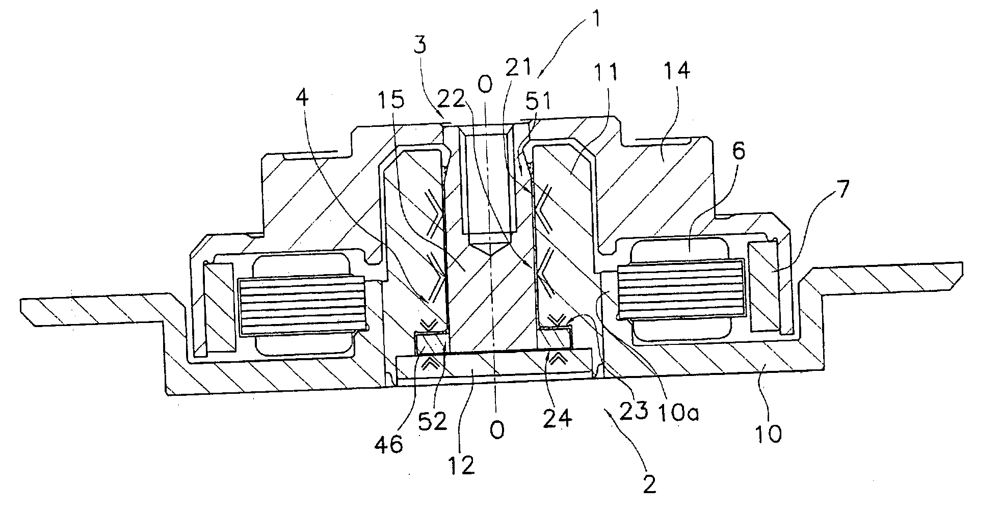
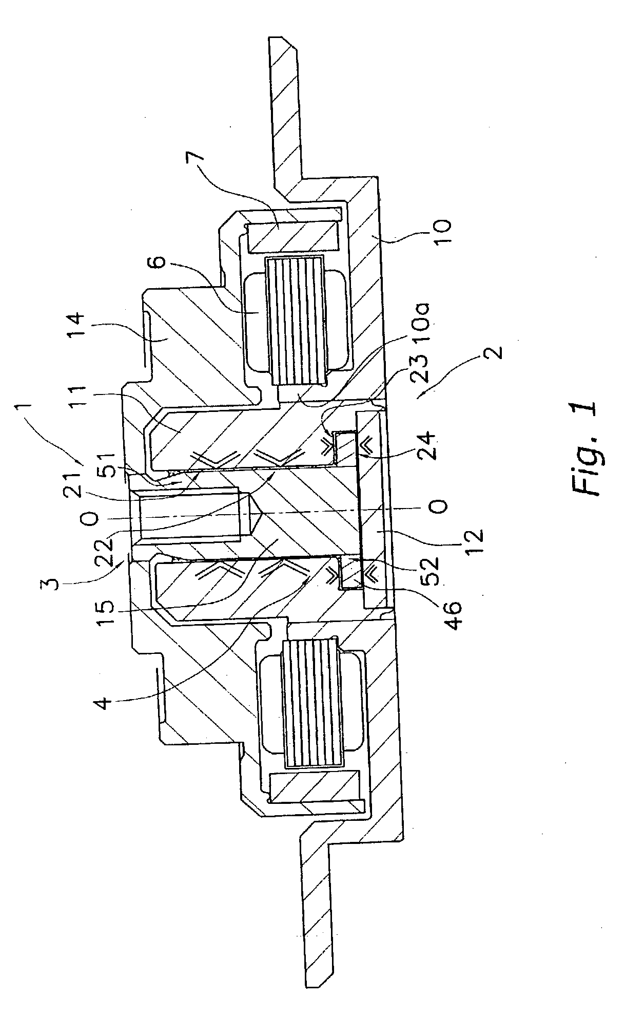
[0044] FIG. 1 is a longitudinal cross-sectional view showing a simplified construction of a spindle motor 1 according to one embodiment of the present invention. The spindle motor 1 is a spindle motor for a recording disk drive and forms a portion of a recording disk drive device such as a hard disk and the like.

[0045] Note that the line O-O shown in FIG. 1 is the axis of rotation of the spindle motor 1. In addition, although the vertical direction in FIG. 1 is described in this embodiment as the axial vertical direction for the sake of convenience, the actual position in which the spindle motor 1 is mounted is not limited thereto.

[0046] In FIG. 1, the spindle motor 1 is primarily comprised of a stationary member 2, a rotary member 3, and a bearing mechanism 4 for supporting the rotary member 3 in the stationary member 2 such that the rotary member 3 is freely rotatable in the stationary member 2. The spindle moto...


PUM

PropertyMeasurementUnit
thicknessaaaaaaaaaa
inner diameteraaaaaaaaaa

Abstract

A method of manufacturing a thrust plate for a dynamic pressure bearing in which the upper and lower end surfaces thereof have a highly precise perpendicular angle relative to the central axis thereof. The thrust plate has an annular shape, and a central hole is formed therein in which is fitted a shaft body. Thrust surfaces that form a portion of thrust bearing units are formed at both end surfaces of the thrust plate. The method of manufacturing the thrust plate includes a blanking step in which a plate-like work piece is press-cut to obtain an annular blank intermediate, an end surface polishing step in which both end surfaces of the blank intermediate are polished, and a shaving step in which an inner hole and an outer periphery of the polished blank intermediate are simultaneously press-cut to shave off surfaces thereof.

Description

BACKGROUND OF INVENTION[0001] 1. Field of the Invention[0002] This invention generally relates to a method of manufacturing a thrust plate for a shaft in a dynamic pressure bearing, the shaft having an annular shaft body in which an outer peripheral surface thereof forms a portion of a radial bearing unit. More particularly, the present invention relates to a method of manufacturing a thrust plate that has an annular shape and a central hole formed therein into which the shaft body is fitted, and which has thrust surfaces formed on both end surfaces thereof that form a portion of a thrust bearing unit.[0003] 2. Background Information[0004] A recording disk drive device for a hard disk and the like includes a spindle motor for rotatively driving a recording disk, and is concentrically disposed with respect to the recording disk. The spindle motor is primarily comprised of a stationary member to which a stator having an armature coil is fixed, a rotary member that is fixed to a rotor ...

Claims


Application Information

Patent Timeline
Patent Type & Authority Applications(United States)
IPC IPC(8): F16C33/14B21D28/00B21D53/10F16C17/10G11B19/20H02K5/16H02K5/167H02K7/08H02K15/14H02K21/22
CPCG11B19/2018H02K15/14H02K5/1675F16C17/107F16C2370/12
Inventor SODE, TAKAYUKIYOSHIZAWA, KENJI
Owner SOODE NAGANO
Why Eureka
Try Eureka