Public key cryptographic systems are designed so that it is easy to generate a random pair of inverse keys PU for enciphering and PR for deciphering and it is easy to operate with PU and PR, but is computationally infeasible to compute PR from PU.
Anyone can now encrypt messages and send them to the user, but no one else can
decipher messages intended for that user.
A problem with a signing protocol making use of CERTs is that it does not automatically protect the privacy of the signer.
Moreover, once you have been reliably identified by your
digital signature and corresponding
certificate you have lost any hope of remaining anonymous or preventing merchants from cross-linking their records about you.
In cyberspace, the most dangerous
threat to your privacy is not a wiretapper, but the other party to your transaction.
It may be computationally impractical to determine the identity of the holder of the
certificate from the distinguished name.
At the same time, it may be very difficult for someone to randomly determine if any user used a particular AC.
Furthermore, it is not possible to decide whether two signatures have been issued by the same group member.
However, these proposed solutions had the following undesirable properties: (1) the length of the group's public key and / or the size of a signature depends on the size of the group, which is problematic for large groups; and (2) to add new group members, it is necessary to modify at least the public key.
EP 1 136 927 A2, and the
group signature scheme of J. Camenisch and M. Stadler, described in their paper "Efficient
group signature schemes for large groups", Proceedings of EUROCRYPT '97, each have the advantageous property that only one registration is required per user, thereby allowing the user to generate a plurality of signatures on a plurality of messages, which are then provided to one or more different receiving systems or users who verify these signatures, these methods have the disadvantageous property that the signature algorithms themselves are relatively new.
As yet, there are no cryptographic standards based on these signature algorithms.
However, there are two problems presented by using the existing PKI and RSA-based CERTs, including pseudonymous CERTs.
For example, the user might share limited demographic information with several different receiving parties, which by itself would not allow any receiving party to learn the user's true identity.
However, if the data associated with a single user can be collected and aggregated, then it may be possible to identify the user on the basis of sophistical analysis techniques, thereby undermining the privacy of the user.
Of course, the proposed method would not prevent or deter the user from making his or her true identity known to the receiving party, if so desired.
One problem with the described method is that each user must have a different public
verification key and different private signature key, and a different pseudonymous CERT for each such public
verification key, containing a different pseudonymous ID, for each receiving party with which the user intends to communicate.
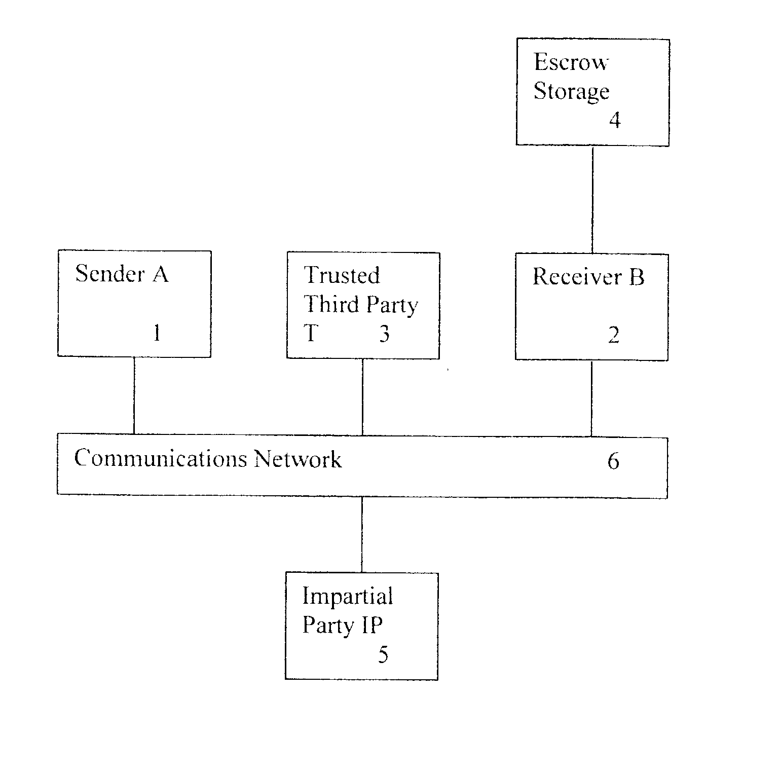
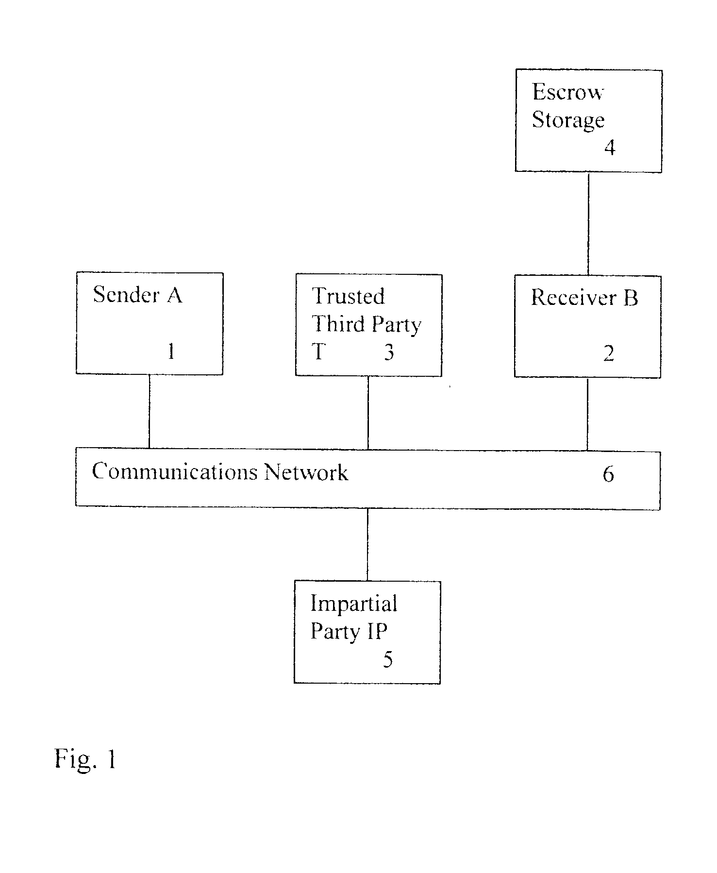
US 2001 / 0039535 A1, U.S. Pat. No. Re. 34,954, U.S. Pat. No. 5,001,752, in addition to others described in the literature, make use of a TTP to "vouch" on behalf of one party to another party, or perform a service on behalf of one party who interacts or communicates with another party, these TTP-based protocols do not offer or provide a solution to the three-party signing protocol.
1. COMPANY generates an agreement, which it encrypts with the symmetric key SYMKEY not known by TP. COMPANY signs the encrypted message and forwards the encrypted message to TP.
2. TP verifies the COMPANY signature and confirms this by signing the encrypted message and forwarding the encrypted message to the related
CLIENT. TP does not know the
encryption key SYMKEY so TP is not able to read the contents of the message.
3.
CLIENT verifies TP's signature (confirming COMPANY signature) and, after checking the agreement, signs the encrypted message and returns the signed encrypted message to TP.
4. TP verifies
CLIENT's signature and the originality of message towards the original message forwarded by COMPANY (i.e., it verifies that the encrypted message received from CLIENT is the same as the encrypted message received from COMPANY). TP now has an encrypted agreement signed by both COMPANY and CLIENT. The encrypted agreement signed by both parties is stored for safekeeping on behalf of both CLIENT and COMPANY (i.e., it is escrowed at TP). TP strips off CLIENT's signature and signs on behalf of CLIENT using the Private Part of the CLIENT VID (using private key Cl.Vir.Pr), and also signs on behalf of himself (using private key TP.Pr) thereby confirming the existence of a signed agreement in safe custody (i.e., escrowed at TP). The encrypted message and signatures are forwarded to COMPANY.
5. COMPANY verifies signatures of VID (using public key Cl.Vir.Pu) and of TP (using public key TP.Pu) confirming the existence of an agreement signed by CLIENT.
Potentially, the generation and management of such a large number of public / private key pairs could add significantly to the cost of operating the TP.
Hence, with respect to keys, the method lacks
scalability.
On the other hand, there seems to be no way to avoid assigning different VIDs for each CLIENT and COMPANY pair.
However, requiring TP to perform this
escrow function again adds to the cost of operating TP.
If TP performs escrowing, then this could lead to an unwieldy coordination problem between COMPANY and TP, since TP would need to
escrow for as long as COMPANY escrows, and it could discard escrowed information only after COMPANY discards escrowed information.
However, solving the
escrow problem is not straightforward, since COMPANY and CLIENT might collude to cheat TP by conveniently misplacing the escrowed copy of CLIENT's signature, or COMPANY may unintentionally misplace the signature.
Another problem with COMPANY performing the total escrow function is that COMPANY would "see" CLIENT's signature.
This would defeat the intended security of the three-party signing protocol.
On the other hand, the RSA signature
algorithm does not produce randomized signatures.



