Spark plug for internal combustion engine

a technology for spark plugs and internal combustion engines, which is applied in the direction of spark plugs, machines/engines, mechanical equipment, etc., and can solve problems such as suitability for practical use and practical us

Inactive Publication Date: 2003-10-16
DENSO CORP
View PDF9 Cites 20 Cited by
  • Summary
  • Abstract
  • Description
  • Claims
  • Application Information

AI Technical Summary

Problems solved by technology

If the cross section of the projection is too small, it is not suitable for practical use, because the projection is not heat resistant.
If the length of the projection is too long, it is not suitable for practical use, because the projection is not heat resistant.

Method used


Image

  • Spark plug for internal combustion engine
  • Spark plug for internal combustion engine
  • Spark plug for internal combustion engine

Examples


embodiment 1

[0049] Embodiment 1

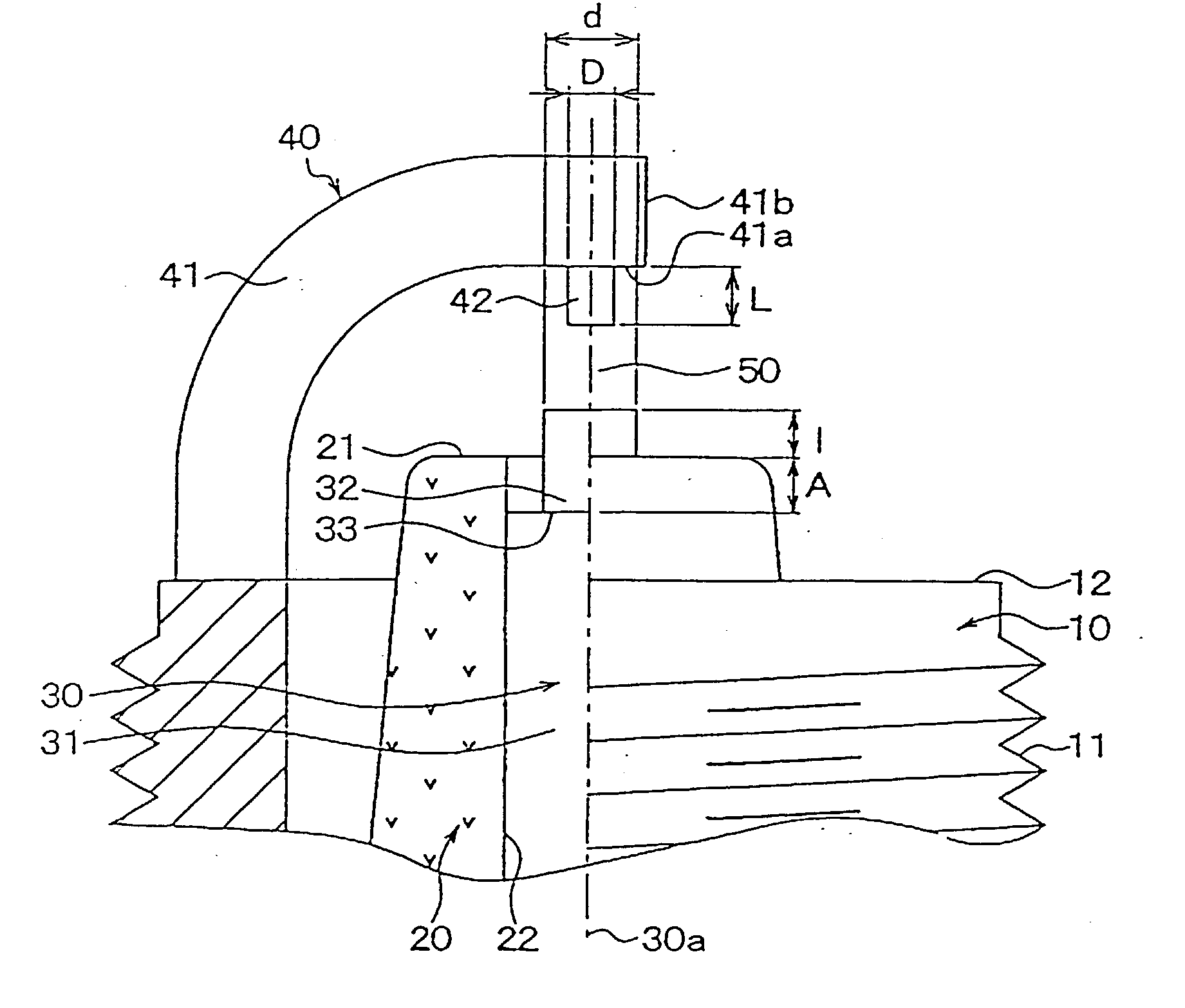
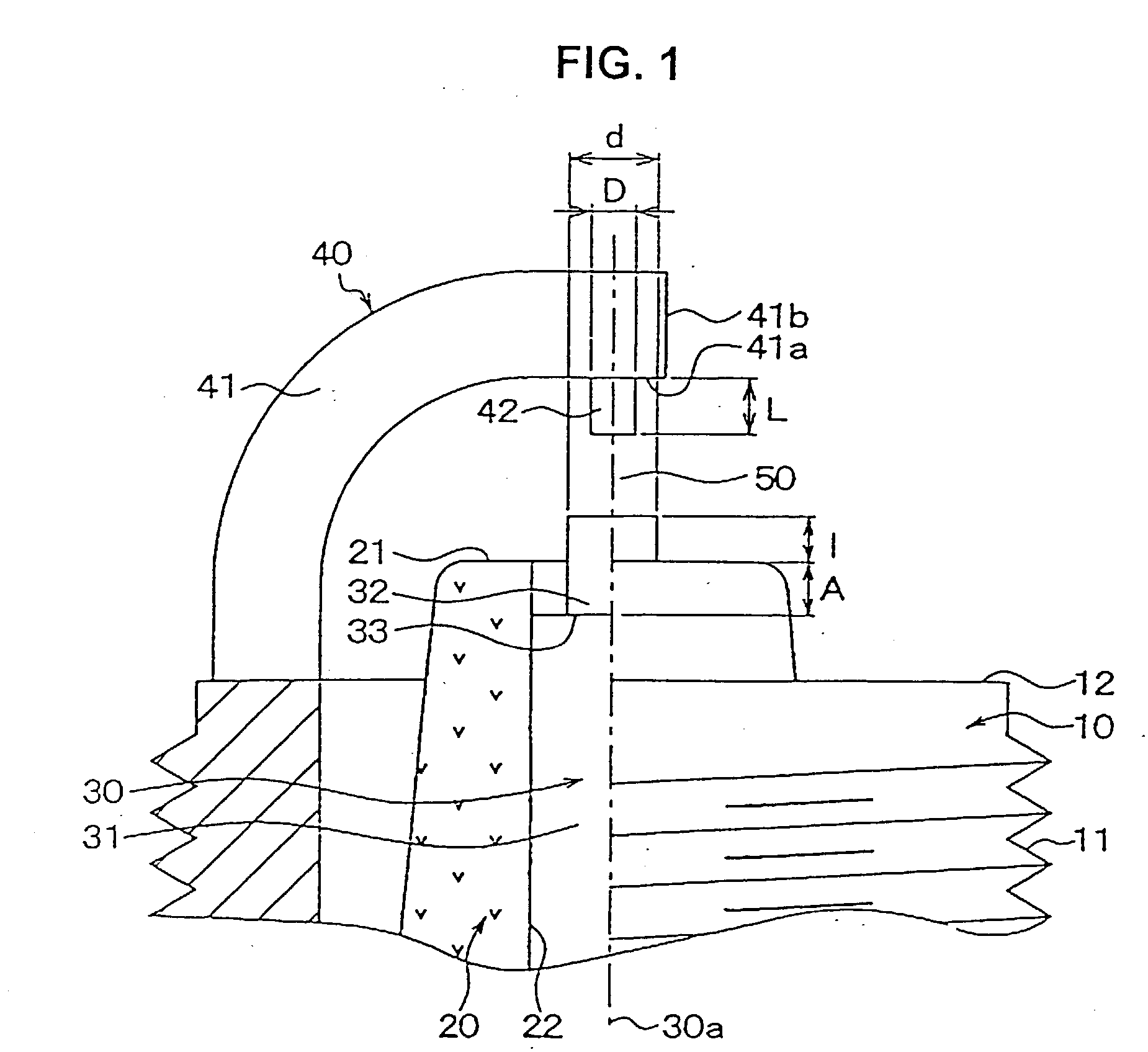
[0050] FIG. 1 is a fragmentary cross sectional view of a main portion of the spark plug of Embodiment 1, wherein a columnar hausing 10 (made of a conductive steel material such as a low carbon steel) is provided with a male screw 11 in order to fix the hausing 10 to a not-shown column head of an internal combustion engine.

[0051] Inside the hausing 10, a columnar insulator 20 made of, e.g., alumina ceramic (Al.sub.2O.sub.3) is fixed. Further, a tip 21 of the insulator 20 is exposed from an edge of the hausing 10.

[0052] The columnar central electrode 30 is fixed in an axial hole 22 of the insulator 20, thereby insulating the insulator 20 from the hausing 10. The inner material of the central electrode 30 is a highly heat conductive material such as Cu, while the outer material thereof is a highly heat resistant and corrosion resistant material such as a Ni base alloy, Fe base alloy, or Co base alloy.

[0053] Further, the central electrode 30 comprises: a columnar body...

embodiment 2

[0085] Embodiment 2

[0086] FIG. 8 shows Embodiment 2, wherein the tip surface of the narrowed portion 32 is positioned in the insulator 20, thereby burning down the carbon fouling adhered on the insulator 20 near the tip of the narrowed portion 32 by the sparks generated between the tip of the narrowed portion 32 and the projection 42. Thus, the burning-down effect is further improved.

embodiment 3

[0087] Embodiment 3

[0088] FIG. 9 shows Embodiment 3, wherein a form of the leg 141 of the earth electrode 40 is different from that in Embodiment 1.

[0089] In Embodiments 1 and 2, the surface 141a opposite to the narrowed portion 32 was made nearly parallel to the reference surface perpendicular to the axis 30a. However, in Embodiment 3, the surface 141a is made tilted to the reference surface, thereby improving heat conductivity due to a shortened length of the leg 41.


PUM


Abstract

Carbon fouling adhered on an insulator tip of a spark plug of the present invention is burnt down by a leak current during an inductive discharge period, due to a promoted ionization before beginning a capacitive discharge, in such an arrangement of a central electrode that a border portion of a body and narrowed portion is positioned in an insulator. The carbon burning-down effect is further improved by a narrow projection provided with an earth electrode, due to increased inductive energy and extended inductive discharge time period. This is because an electric field in a discharge gap is raised, thereby decreasing a discharge voltage and suppressing an energy emitted from a coil during the capacitive discharge.

Description

[0001] 1. Field of the Invention[0002] The present invention relates to a spark plug for an internal combustion engine.[0003] 2. Description of the Related Art[0004] There is disclosed in Japanese Patents No. 2727558 and 2805781 a spark plug for an internal combustion engine wherein carbon fouling (contamination) on an insulator tip is burned down by sparks generated during a spark discharge in a discharge gap.[0005] Concretely, an atmosphere around electrodes is ionized by a leak current flowing through the carbon fouling from a time when a high voltage is applied to the electrodes to a time when a capacitive discharge is caused at tips of the electrodes. Then, when an inductive discharge is caused following the capacitive discharge, the carbon fouling on the insulator around the central electrode is burned down, thereby recovering an insulating resistance.[0006] The central electrode of the spark plug is provided with a narrowed portion (narrower than a body) extending to the eart...

Claims


Application Information

Patent Timeline
Patent Type & Authority Applications(United States)
IPC IPC(8): F02P13/00H01T13/20H01T13/34H01T13/39
CPCH01T13/39
Inventor SHIBATA, MASAMICHIHORI, TSUNENOBU
Owner DENSO CORP
Why Eureka
Try Eureka