Surgical drape

a surgical drape and drape technology, applied in the field of surgical drapes, can solve the problems of substantial risk that the drape or a portion of it will move, defeat the effectiveness of the sterility maintenance cover, and increase the risk of infection

Inactive Publication Date: 2003-10-23
NIMED
View PDF15 Cites 77 Cited by
  • Summary
  • Abstract
  • Description
  • Claims
  • Application Information

AI Technical Summary

Problems solved by technology

Improper draping can cause serious problems and defeat the effectiveness of the sterility maintenance cover.
For example, a conventional surgical drape applied insecurely over a sterility maintenance cover creates a substantial risk that the drape or a portion of it will move, exposing all or part of the patient's head during surgery.
Various forces applied directly or indirectly to the drape by surgeons, assistants, instrumentation and the like may cause such movement.
The exposure can contaminate a sterile field, increasing risk of infection, and expose the patient's head to blood and other bodily fluids.
Similarly, applying conventional flat sheet surgical drapes over a three-dimensional sterility maintenance cover may create unintended gaps, exposing all or part of the patient's head during surgery.
Again, the exposure can contaminate a sterile field, increasing risk of infection, and expose the patient's head to blood and other bodily fluids.
For example, a nasal cannula or mask may come lose during surgery thereby preventing a patient from properly receiving supplemental oxygen and possibly trapping dangerous concentrations of oxygen under the drape.
Even worse, a patient may vomit during surgery (e.g., if there is food in an anesthetized patient's stomach) with the stomach contents entering the windpipe and lungs, possibly causing pneumonia or even death.
From the patient's perspective, particularly a patient who is awake at the start or throughout their surgery, such visual concealment deprives the patient of the opportunity to talk with the circulating nurse and may create a sense of claustrophobia, while contributing to anxiety and panic.
Such emotional responses can adversely affect blood pressure and heart rate, which may also complicate a procedure.
Furthermore, conventional surgical drapes, which do not include openings that correspond to openings in a sterility maintenance cover, may cause unwanted increases in temperature and buildup of gasses.
For example, a patient's exhalation under such a drape can make a patien

Method used


Image

  • Surgical drape
  • Surgical drape
  • Surgical drape

Examples


Embodiment Construction

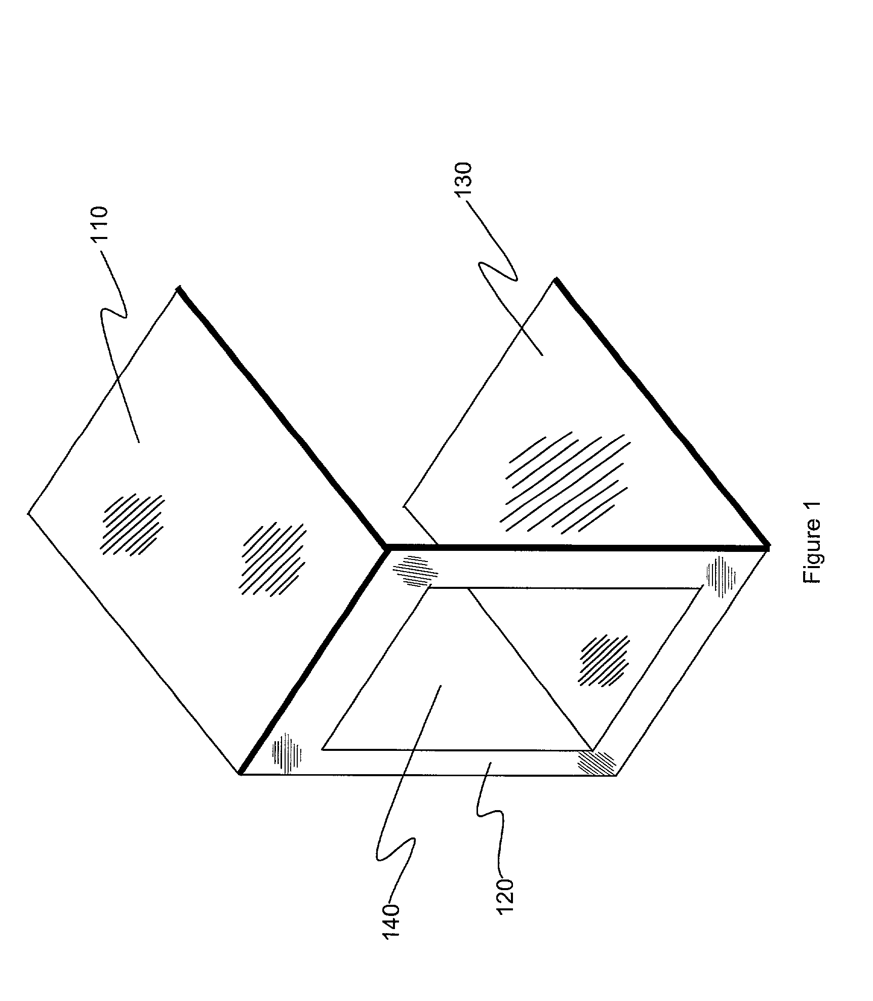
[0026] Referring now to FIG. 1, an exemplary sterility maintenance cover for use in connection with a surgical drape according to the present invention is conceptually shown. The sterility maintenance cover generally includes (i) a base panel 130 for fitting under the head, neck and shoulders of a patient positioned on an examination or operating table, (ii) an upward-standing end panel 120 extending from the base panel and having an open window 140 for accessing the patient from the head-end of the table, and (iii) a cantilevered platform 110 projecting horizontally from the end panel, substantially parallel to the base panel. Preferably, platform 110 is designed to support a drape over a patient's head and to receive and retain or deploy various instruments used in the procedure.

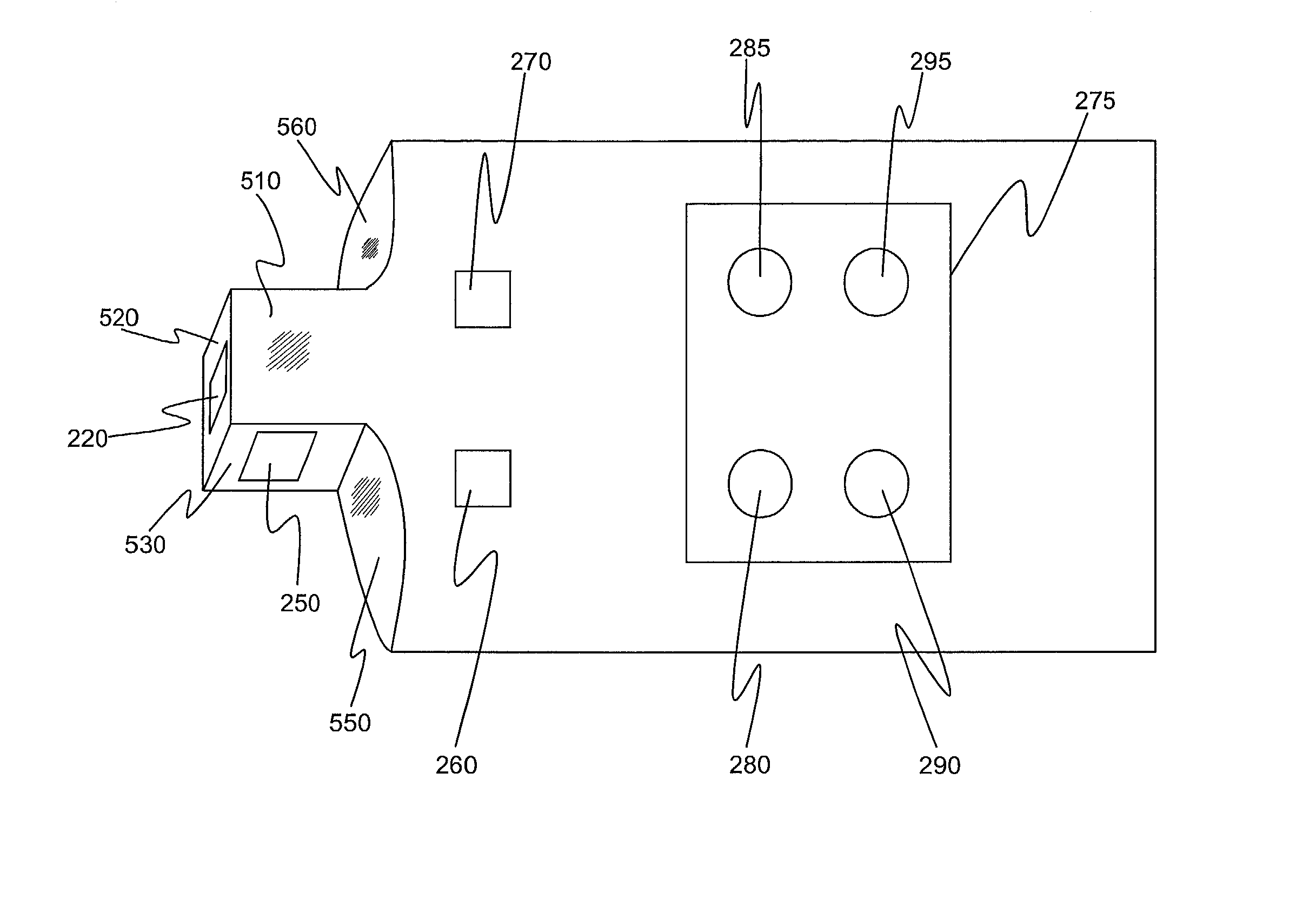
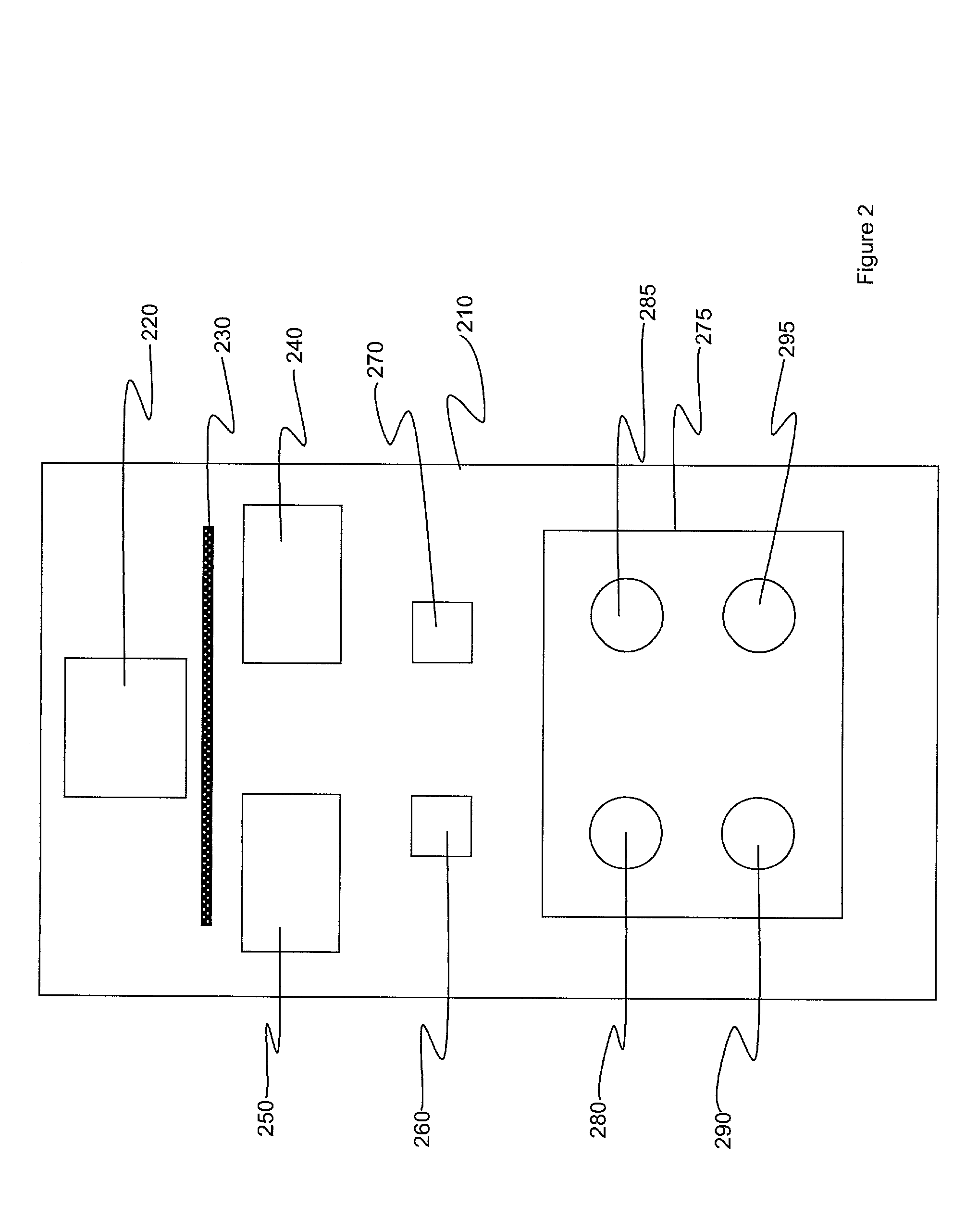
[0027] Now referring to FIG. 2, a top plan view of an exemplary surgical drape 210 in accordance with a preferred embodiment of the present invention is shown. The drape 210 preferably includes an open win...


PUM


Abstract

A surgical drape for use in connection with a sterility maintenance cover has an opening that corresponds to an open window in a sterility maintenance cover to facilitate ventilation and access to a patient's head, a window that corresponds to a window in a sterility maintenance cover to enhance patient comfort and observation, and attachment means for releasably attaching the drape to a sterility maintenance cover, and one or more fenestrations to facilitate surgical access at desired locations.

Description

[0001] 1. Field of the Invention[0002] The present invention relates generally to surgical drapes. More particularly, the present invention relates to a surgical drape for use with a sterility maintenance cover.[0003] 2. Background Description[0004] During certain surgical procedures, such as pacemaker implants and similar procedures, it is imperative that a patient's head be draped in a sterile manner to insure that a sterile field is maintained throughout the operation. Various methods have been employed to achieve this result, including various types of draping techniques, using supports and other devices. For example, U.S. Pat. No. 5,322,072 to Harrison et al. and U.S. Pat. No. 5,546,961 to Harrison (the "Harrison patents") teach sterility maintenance covers that support a surgical drape over a patient's head. Such a sterility maintenance cover generally includes (i) a base panel for fitting under the head, neck and shoulders of a patient positioned on an examination or operatin...

Claims


Application Information

Patent Timeline
IPC IPC(8): A61B19/00A61B19/02A61B19/08A61B46/23
CPCA61B19/0256A61B2017/00902A61B19/10A61B19/08A61B46/23A61B50/20A61B46/00
Inventor HARRISON, SAMUEL W.QUICK, PATRICK SR.BAUCUM, RALPH W. III
Owner NIMED
Why Eureka
Try Eureka