
Method for producing organic electroluminescent device and transfer material used therein

a technology of electroluminescent devices and transfer materials, which is applied in the manufacture of electrode systems, electric discharge tubes/lamps, other domestic objects, etc., can solve the problems of poor productivity, insufficient durability of organic light-emitting devices, and serious problems, and achieve good adhesion interface, good light-emitting efficiency, and low cost

Inactive Publication Date: 2003-12-04
UDC IRELAND
View PDF4 Cites 16 Cited by
  • Summary
  • Abstract
  • Description
  • Claims
  • Application Information

AI Technical Summary

Benefits of technology

[0009] Accordingly, an object of the present invention is to provide a method for forming an organic layer on a substrate by a simple apparatus at a low cost, thereby producing a uniform organic electroluminescent device with a good adhesion interface with a substrate, particularly to a method for producing an organic electroluminescent device excellent in light-emitting efficiency, the uniformity of light emission and durability by forming a uniform organic layer on a substrate.

Problems solved by technology

However, these methods are poor in productivity because they use a vapor deposition method.
In addition, because only low-molecular-weight organic compounds can be used for organic layers in a vapor deposition method, the resultant organic light-emitting devices are insufficient in durability such as bending resistance, film strength, etc., when used for flexible displays, etc.
This problem is serious particularly when they have large areas.
However, because the vapor deposition method cannot be used to form the organic light-emitting thin-film layers, thin-film layers are formed directly on substrates by wet methods.
The wet methods are, however, disadvantageous in that the formed organic layers are insufficient in the uniformity of thickness because of the surface tension of solutions, and that when a new liquid organic layer is laminated on the already solidified organic layer, the solidified organic layer tends to be dissolved in its interface with the new liquid organic layer.
Accordingly, the organic electroluminescent devices obtained by the wet methods are poor in light-emitting uniformity, light-emitting efficiency and durability of devices.
Such a thermal transfer method is disadvantageous in that a gas often penetrates into an interface between the organic layer and the substrate, resulting in poor light-emitting properties.
In addition, there is a problem that the light-emitting efficiency, durability and the uniformity of the organic EL device vary depending on the conditions of the interface of the organic layer.
In the case of thermal writing in a predetermined pattern using a thermal head or a laser common in printing technologies, a temperature distribution generated around an organic, thin-film pattern by thermal diffusion blurs its outline, failing to cut the organic, thin-film pattern from the donor accurately.
Thus, organic light-emitting devices produced by this method are uneven in light emission and likely to suffer from poor durability, because of insufficient electric connection and the breakage of the organic layer.
Further, yield is likely to be low because of low-accuracy positioning of the substrate and the thermal head or laser beam.

Method used


Image

  • Method for producing organic electroluminescent device and transfer material used therein
  • Method for producing organic electroluminescent device and transfer material used therein
  • Method for producing organic electroluminescent device and transfer material used therein

Examples


example 2

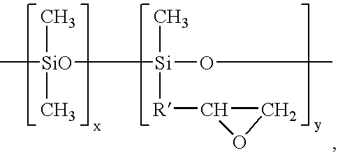
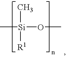
[0189] A transfer material and an organic electroluminescent device were produced and evaluated in the same manner as in Example 1 except for using a coating solution 2 for a peeling layer having a composition of 18 parts by mass of a polyester resin HP301 having a glass transition temperature of 62.degree. C. and a softening point of 105.degree. C. available from The Nippon Synthetic Chemical Industry Co., Ltd., 2 parts by mass of silicone (Orgatics SI220 available from Matsumoto Trading Co., Ltd.) reacting with a peeling layer-forming resin, 40 parts by mass of methyl ethyl ketone, and 40 parts by mass of toluene, in place of the coating solution 1 for a peeling layer. The results are shown in Table 1.

example 3

[0190] A transfer material and an organic electroluminescent device were produced and evaluated in the same manner as in Example 1 except for using a coating solution 3 for a peeling layer having a composition of 17 parts by mass of a polyester resin HP320 having a glass transition temperature of 62.degree. C. and a softening point of 95.degree. C. available from The Nippon Synthetic Chemical Industry Co., Ltd., 3 parts by mass of silicone oil KF54 available from Shin-Etsu Chemical Co., Ltd., 40 parts by mass of methyl ethyl ketone, and 40 parts by mass of toluene, in place of the coating solution 1 for a peeling layer. The results are shown in Table 1.

example 4

[0191] A transfer material and an organic electroluminescent device were produced and evaluated in the same manner as in Example 1 except for using a coating solution 4 for a peeling layer having a composition of 15 parts by mass of a polyester resin HP301 having a glass transition temperature of 62.degree. C. and a softening point of 105.degree. C. available from The Nippon Synthetic Chemical Industry Co., Ltd., 5 parts by mass of vinyl-modified silicone XF40-A1987 available from GE Toshiba Silicones Co., Ltd., 0.01 part by mass of a platinum catalyst, 40 parts by mass of methyl ethyl ketone, and 40 parts by mass of toluene, in place of the coating solution 1 for a peeling layer. The results are shown in Table 1.


PUM

PropertyMeasurementUnit
Thicknessaaaaaaaaaa
Thicknessaaaaaaaaaa
Thicknessaaaaaaaaaa

Abstract

A transfer material comprises a temporary support and an electroluminescent element layer, and positioned between said temporary support and said electroluminescent element layer. Using the above transfer material, an organic electroluminescent device is produced by a method comprising the steps of superposing the transfer material on an electrode layer side of a substrate has partially or wholly transparent or opaque electrode layer, contacting the transfer material and the substrate, and transferring at least one electroluminescent element to the electrode layer side of a substrate with at least one heating means and pressing means.

Description

[0001] The present invention relates to a transfer material being capable of making an organic electroluminescent device, and a method for producing an organic electroluminescent device comprising such a transfer material.[0002] Much attention is paid to organic light-emitting devices such as organic electrolurminescence (EL) devices usable for flat panel display devices. Specifically, promising as inexpensive, solid-emission-type, large-emission-area, full-color display devices and writing light source arrays, the organic light-emitting devices have been actively developed.[0003] The organic light-emitting device generally comprises a couple of electrodes (a transparent electrode and a rear-surface electrode), and a light-emitting organic layer formed between the electrodes. When an electric field is applied to the organic light-emitting device between a pair of opposing electrodes, electrons are injected into the light-emitting device from the rear-surface electrode, while holes a...

Claims


Application Information

Patent Timeline
IPC IPC(8): H01L51/40H01L51/56
CPCH01L51/0013Y10S428/914H01L51/56H10K71/18H10K71/40H10K71/00
Inventor TATEISHI, TOMOMIYAMADA, MAKOTONISHITA, NOBUHIRO
Owner UDC IRELAND
Learn More