Condenser microphone structure

Active Publication Date: 2003-12-04
PANASONIC CORP
View PDF5 Cites 1 Cited by
  • Summary
  • Abstract
  • Description
  • Claims
  • Application Information

AI Technical Summary

Benefits of technology

[0009] It is, therefore, an object of the present invention to provide a condenser microphone structure which can reduce high frequency noises to as a small level as possible.
[0011] It is a further object of the present invention to provide a condenser microphone structure which can realize a stable electrical connection between the elements or parts forming part of the condenser microphone structure.

Problems solved by technology

The conventional condenser microphone structure, however, encounters such problems that the condenser microphone tends to receive high frequency noises through the terminal connecters other than voice sounds, resulting from the fact that the terminal connecters each made of a metal plate material has a relatively large surface area.
The metal mold high in precision needed for production of the conventional microphone structure leads to the fact that the metal mold inevitably becomes at a markedly high production price and needs a relatively long production period for producing the metal mold and punching and bending a sheet metal.
In the case of the metal mold low in precision, on the other hand, unstable electric connections are liable to be caused between the terminal connecters and the board terminals and between the terminal connecters and the condenser microphone when the terminal connecters terminal connecters are assembled with the insulator and the condenser microphone.

Method used


Image

  • Condenser microphone structure
  • Condenser microphone structure
  • Condenser microphone structure

Examples


Embodiment Construction

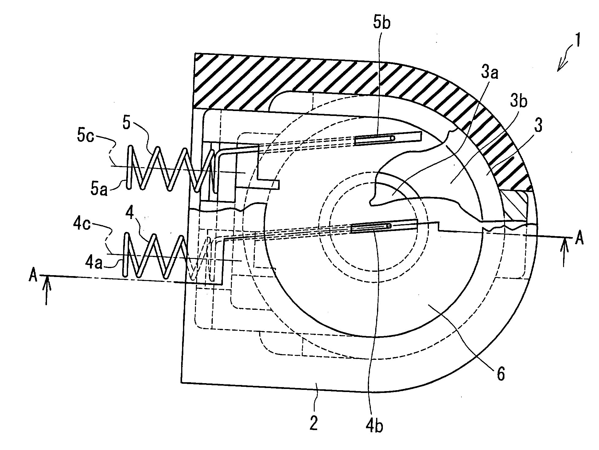
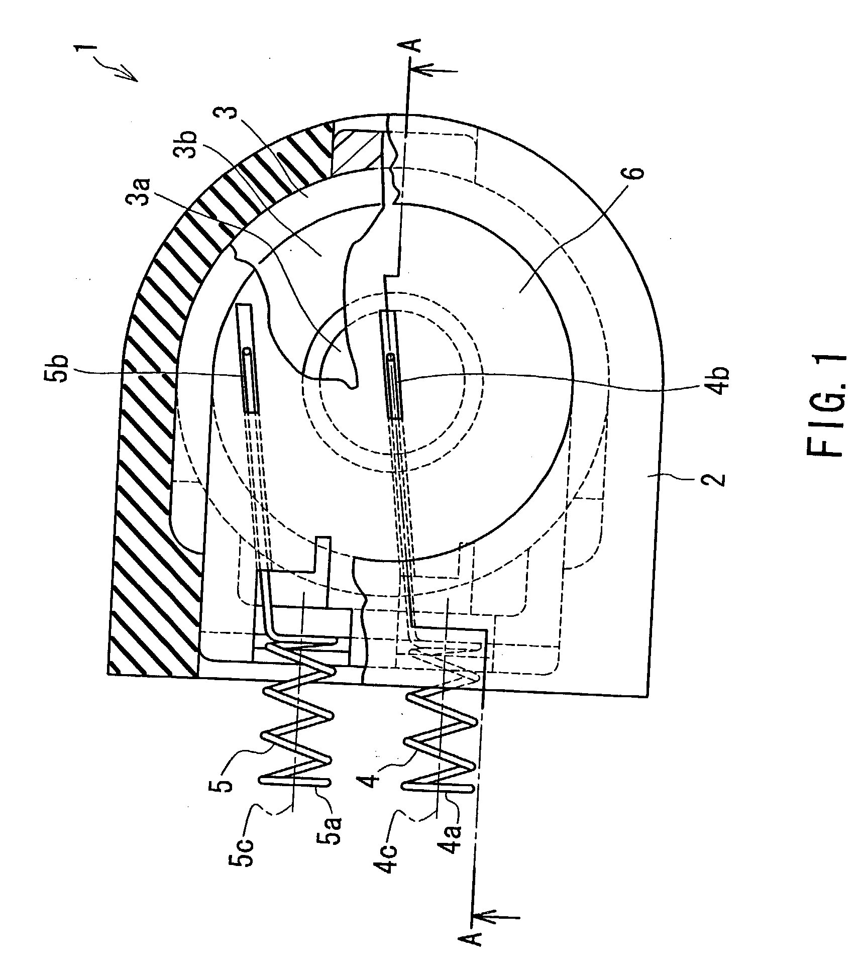
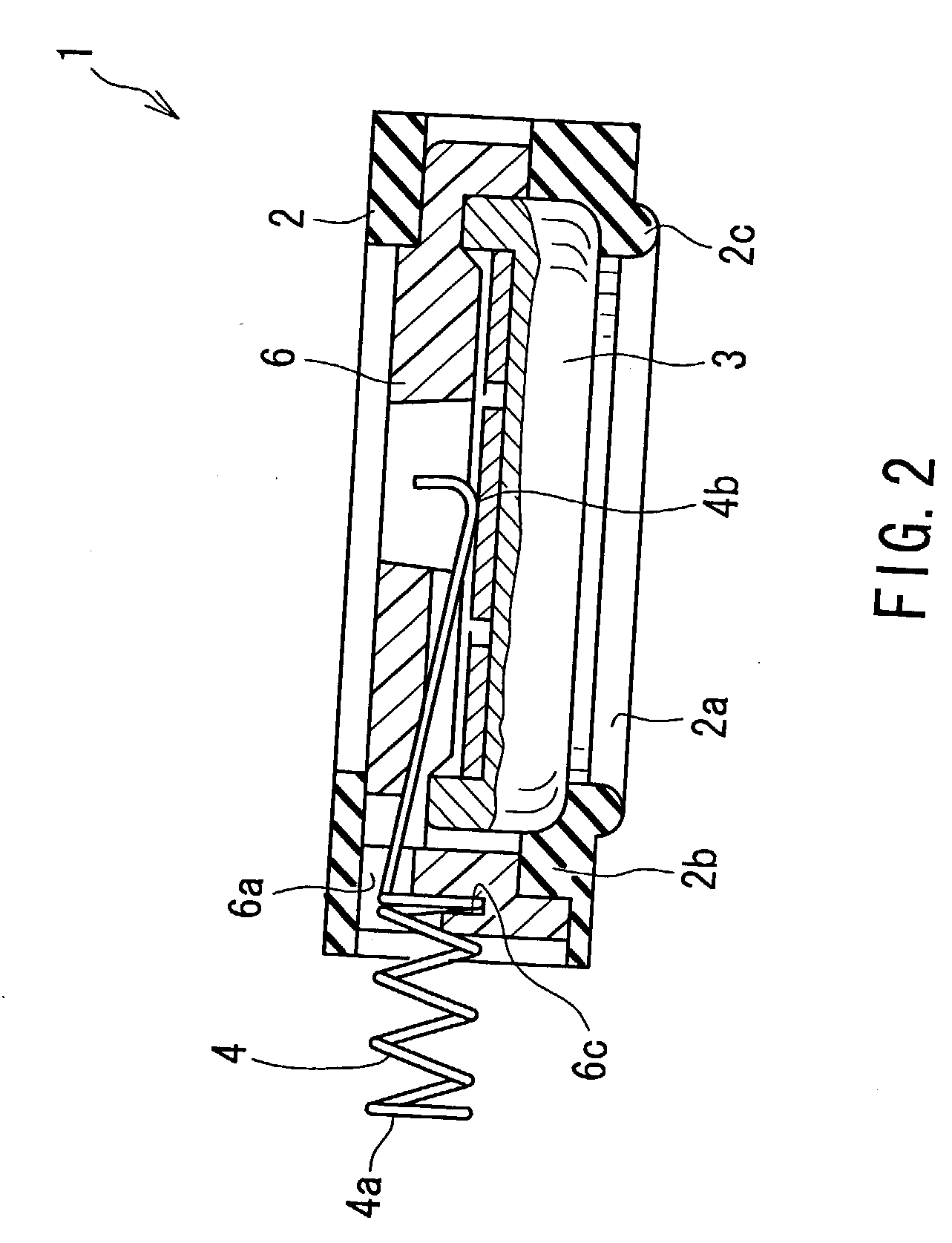
[0028] One embodiment of the condenser microphone structure according to the present invention will be described hereinafter with reference to the drawings, particularly to FIGS. 1 to 3. Throughout the following detailed description, similar reference numbers refer to respective similar elements in all figures of the drawings.

[0029] The embodiment of the condenser microphone structure 1 is shown in FIGS. 1 and 2 as comprising a microphone housing 2 formed with an opening 2a, and a condenser microphone 3 accommodated in the microphone housing 2 and partly exposed to the exterior through the opening 2a so that the condenser microphone 3 is capable of receiving a voice sound through the opening 2a to produce a sound signal indicative of the voice sound. The microphone housing 2 is made of a resilient material such as for example rubber and synthetic resin, and has an open end opened toward a printed circuit board unit 12 which becomes apparent as the description proceeds. The microphon...


PUM


Abstract

Herein disclosed is a condenser microphone structure which comprises a microphone housing, a condenser microphone accommodated in the microphone housing to produce a sound signal indicative of a voice sound, first and second terminal connecters provided on the microphone housing in the neighborhood of each other under an insulated state from each other, each of the first and second terminal connecters including a helical spring portion, and an end portion integrally formed with the helical spring portion, the helical spring portion and the end portion being made of an electrically conductive material, the end portions being electrically connected with the condenser microphone to discharge the sound signal from the condenser microphone through the first and second terminal connecters, and an insulating member accommodated in the microphone housing to retain the condenser microphone and the first and second terminal connecters with the microphone housing and to insulate the first terminal connecter from the second terminal connecter. The condenser microphone thus constructed can cause high frequency noises to be reduced to as a small level as possible, and can be produced at a relatively low production price and at a considerably short production period.

Description

[0001] 1. Field of the Invention[0002] The present invention relates to a condenser microphone structure, and more particularly to a condenser microphone structure to be assembled in a cellular phone with high frequency noises reduced to as a small level as possible.[0003] 2. Description of the Related Art[0004] As such a conventional condenser microphone structure assembled in a cellular phone to enable communications with other cellular phones, there has so far been proposed and developed a wide variety of condenser microphone structures which are known as being small in size and as having one or more terminal connecters electrically connected with parts or elements forming part of the cellular phone.[0005] One of the typical examples of the condenser microphone structures thus known is shown in FIGS. 10 and 11 as comprising a housing 51, a condenser microphone 52 accommodated in the housing 51, an insulator 53 made of a synthetic resin material and also accommodated in the housin...

Claims


Application Information

Patent Timeline
IPC IPC(8): H04R19/04H04R1/06
CPCH04R1/06
Inventor HOHJYO, MASAYOSHI
Owner PANASONIC CORP
Why Eureka
Try Eureka