Transmission apparatus

a technology of transmission apparatus and transmission device, which is applied in the direction of data switching network, frequency-division multiplex, instruments, etc., can solve the problems of not being able to fully manage the entire network, not being able to greatly reduce the capital cost and running cost of an optical network for transmitting ip signals, and not being able to achieve the effect of greatly reducing the capital cost and running cost of an optical network

Inactive Publication Date: 2003-12-11
FUJITSU LTD
View PDF6 Cites 40 Cited by
  • Summary
  • Abstract
  • Description
  • Claims
  • Application Information

AI Technical Summary

Problems solved by technology

In other words, they can only manage networks at the transmission control protocol / IP (TCP / IP) layers.
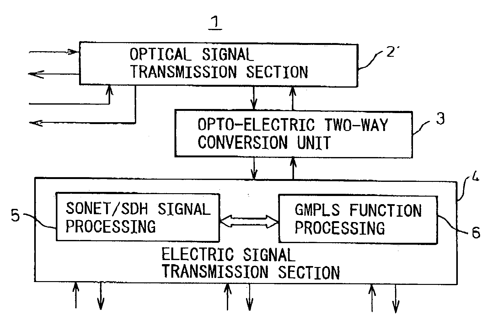
As will become evident later, however, in the past, no technique has been proposed enabling entire networks to be integrally managed by having single transmission apparatuses perform processing for the SONET / SDH / WDM layers and the TCP / IP layers.
In the final analysis, there has therefore been the problem that it has not been possible to greatly reduce the capital costs and running costs of an optical network for transmitting IP signals.
The truth is, however, that an O-UNI or overlay model does not achieve the object of truly integrated network management.
Further, if trying to complicatedly manage a network by pure light type network nodes as proposed by Nortel, it would be necessary to install optical detectors throughout the optical paths to monitor the state of the optical signals.
This would conversely invite an increase in the cost of the hardware.
However, these only simply integrate OXC apparatuses and LSR's of the MPLS.
Further, each of the above apparatuses and concepts proposed as PEER models for GMPLS fundamentally have the following disadvantage.
If trying to introduce OXC having such special LSR functions, there is the disadvantage that this existing equipment would have to be replaced.
This however would force a considerable cost burden on the telecommunication carriers.
No such hardware concept however has yet been proposed anywhere.
No such hardware, however, has been proposed anywhere either.
This model, however, establishes a protocol completely occupying a certain wavelength at the entrance to the WDM network, so does not allow the IP MPLS paths to be freely controlled or faults to be bypassed at the WDM network.
Therefore, the above object cannot be achieved.
In this case, if managing the network from the standpoint of managing LSR's, unless adding the functions of LSR's to all of the nodes (NE) of the optical network, integrated network management cannot be achieved.
Further, the above-explained O-UNI of FIG. 22 (overlay model) is not sufficient for managing a network as a whole.
However, leaving aside just switching entire wavelengths, efficiently controlling the MPLS path level independently and efficiently allocating traffic to the non-used time division multiplex (TDM) regions are extremely difficult techniques.
To realize this, it would be necessary to provide detectors for detecting the state of the light all around the place, provide optical memories, which still cannot be said to be sufficiently at the practical stage, in the optical paths of the apparatuses, or use sophisticated technology thereby making the apparatuses much higher in cost.
This is not good for the telecommunication carriers and in turn for the users.
As explained above, however, if assuming the provision of OXC functions, integrated network management would become impossible to realize unless replacing these WDM nodes with photonic nodes (NE) with OXC apparatuses.
This would similarly not only force a large investment burden on the telecommunication carriers, but would also not be of any merit to the users.
Some apparatuses proposed in the past were integrated OXC and LSR apparatuses, but as explained above these could not perform functions required in WDM network management such as cooperation in bypassing of line faults at the SONET / SDH layer and bypassing of line faults at the MPLS paths or setting of paths at the SONET / SDH layer in accordance with MPLS paths.
An optical signal has the merit of faster and easier signal transmission and processing compared with an electrical signal, but has the demerit of difficult buffering.
stuffing the IP's of the same route (GMPLS) in a single wavelength would be inefficient, so for finer IP traffic engineering, the corresponding WDM optical signals are converted to electrical signals for processing.
In the case of electrical signals, however, there are limits to the speed of processing compared with optical signals (limit of several 10 s of GHz), so it is necessary to suitably convert the electrical signals from a serial to parallel (S / P) format to lower the speed for processing.
If converting to a parallel format for lowering the speed, however, the number of signal lines required inevitably ends up increasing
Therefore, if trying to increase the switch (cross connect) capacity as much as possible (to over the Terabyte level), sooner or later the number of signal lines will become a bottleneck.
In this case, the merits of the memory function, a basic feature natural in electrical signals, but difficult with optical signals, become tremendous, so there is a tradeoff between optical signal processing and electrical signal processing.
Therefore, this is a case where a transport network does not compatible with TCP / IP routing table or MPLS.
The reason is that with a conventional SONET / SDH layer or WDM layer, it is only possible to secure a fixed bandwidth.
The layer is not suited to statistical multiplexing like demands such as for flexibly dealing with temporal fluctuations in traffic.
In a transport network supporting only the SONET / SDH or WDM optical packet layer, it is necessary to constantly secure bandwidth (regardless of the traffic flowing through the path), so it is not possible to efficiently utilize the network resources.

Method used


Image

  • Transmission apparatus
  • Transmission apparatus
  • Transmission apparatus

Examples


Embodiment Construction

[0182] Before explaining the detailed example, the differences between the prior art and present invention will be clarified.

[0183] As explained above, the characteristics of the LSR of FIG. 24 having a configuration closest to the present invention will be analyzed here. That is, the LSR collects the topology information of the entire MPLS layer including the topology of the optical network and uses this for integral network management.

[0184] That is, the TE topology database of FIG. 24 stores the topology information of the network as a whole. Topology information is swapped with different routers. The databases of all routers are combined for use. Therefore, the broader the range covered by the network, the larger the capacity of the database and further the more different routers have to communicate with each other. Therefore, the processing handled by traffic engineering control in the figure also ends up becoming heavier. The present invention provides a transmission apparatus...


PUM


Abstract

A transmission apparatus for coupling an optical signal transmission section and an electrical signal transmission section through an opto-electric two-way conversion unit, where the electrical signal transmission section is comprised of a SONET / SDH signal processing function unit and a generalized multi protocol label switching (GMPLS) function processing function unit cooperating with that function unit and where the optical signal transmission section is comprised of an optical add / drop function unit for transferring an optical signal with the electrical signal transmission section through the conversion unit and an optical cross-connect function unit for switching paths in wavelength units of the optical signal with the electrical signal transmission section, whereby the capital cost and running costs of an optical network for transmitting an IP signal can be greatly reduced.

Description

[0001] 1. Field of the Invention[0002] The present invention relates to a transmission apparatus, more particularly relates to a transmission apparatus provided with a synchronous optical network / synchronous digital hierarchy (SONET / SDH), wavelength division multiplexing (WDM), or other interface[0003] As such transmission apparatuses, in general, there are add-drop multiplexer (ADM) apparatuses, cross-connect apparatuses, optical ADM (OADM) apparatuses, optical cross-connect (OXC) apparatuses, etc. Further, in the present invention, the transmission apparatuses include transmission apparatuses for adding / dropping, cross-connecting, or switching plesiochronous digital hierarchy (PDH) signals, asynchronous transfer mode (ATM) signals, and Ethernet signals. Further, the present invention may also include all sorts of transmission apparatuses (communication apparatuses) for transmitting Internet protocol (IP) signals[0004] 2. Description of the Related Art[0005] Conventional SONET / SDH ...

Claims


Application Information

Patent Timeline
Patent Type & Authority Applications(United States)
IPC IPC(8): G02B6/28H04B10/27H04B10/275H04B10/291H04J3/00H04J14/02H04L12/42H04L12/43H04L12/701
CPCH04J14/0201H04J14/0241H04J14/0283H04J14/0284H04J14/0286H04J14/029H04J14/0291H04J14/0294H04J14/0295H04J2203/0042H04J2203/006H04J2203/0096H04L12/43H04L2012/5652H04L2012/5665H04J14/0227
Inventor NOTANI, MORIHITO
Owner FUJITSU LTD
Why Eureka
Try Eureka