

Limiting amplifier with a power detection circuit
- Summary
- Abstract
- Description
- Claims
- Application Information
AI Technical Summary
Problems solved by technology
Method used
Image

Examples
first embodiment
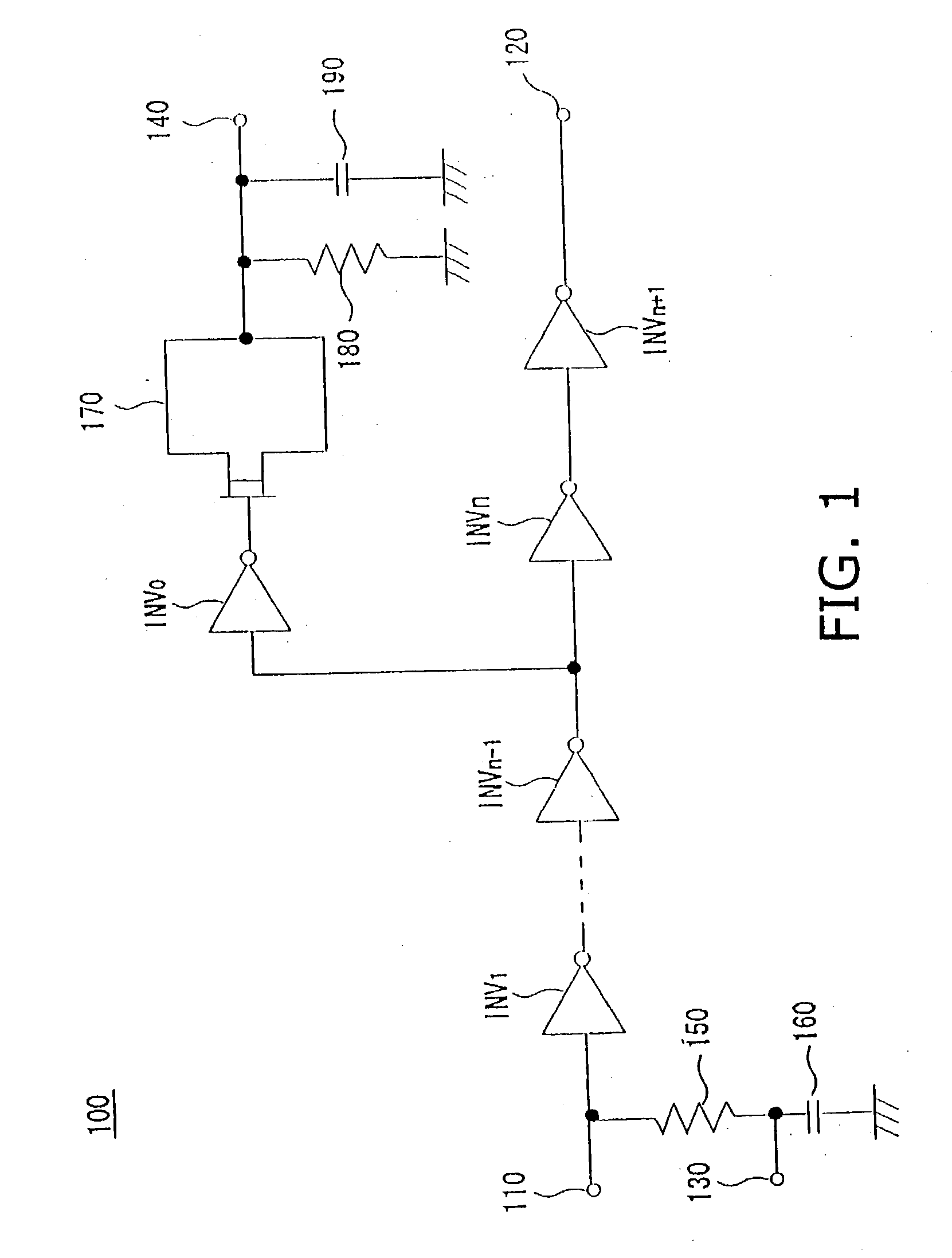
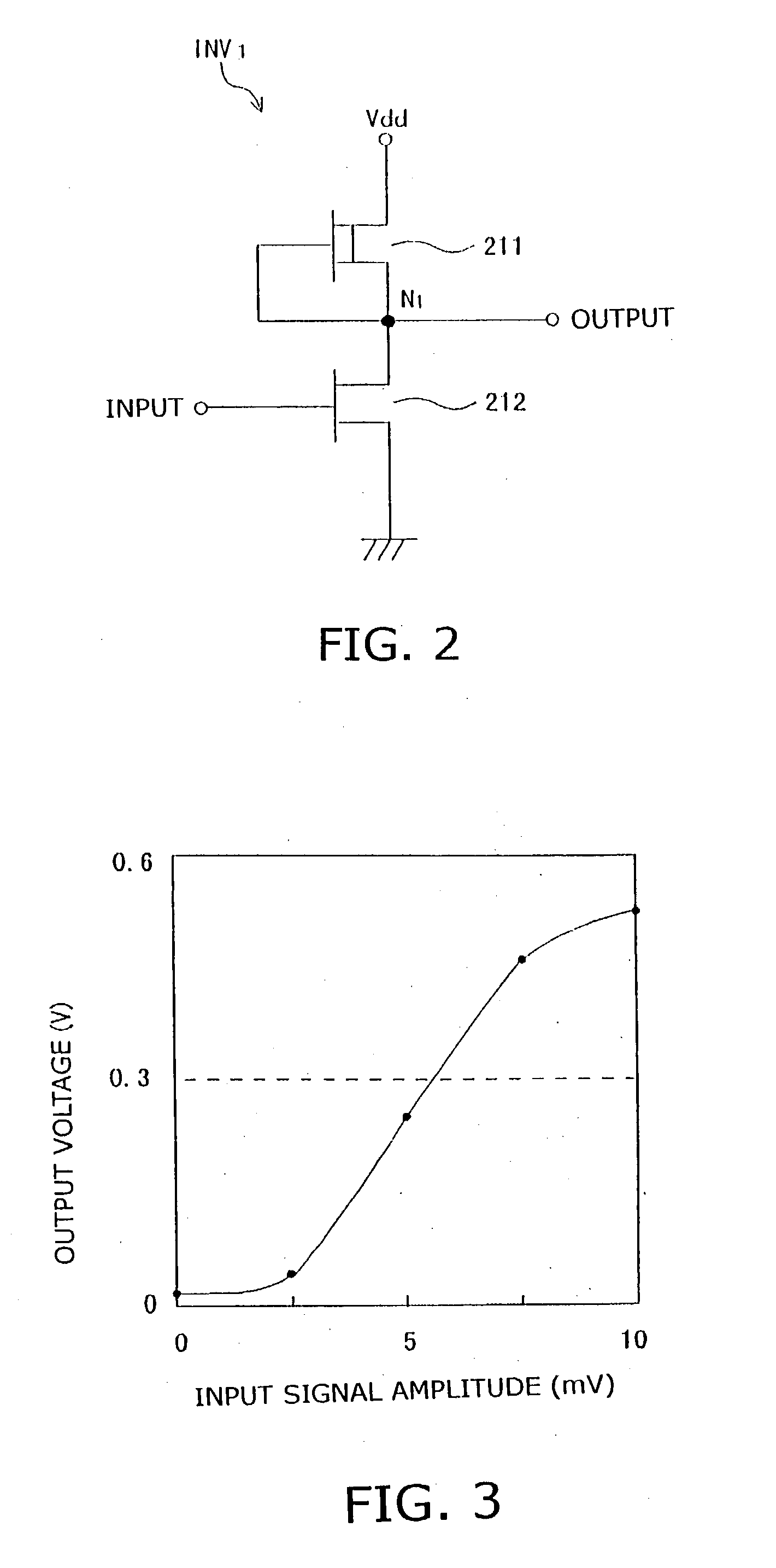
[0024] A limiting amplifier with a power detection circuit according to the invention will be described with reference to FIGS. 1-3.
[0025] In FIG. 1, a limiting amplifier with a power detection circuit 100 comprises a signal input terminal 110, a signal output terminal 120, a reference potential terminal 130, a power output terminal 140, a resistor 150, a capacitor 160, inverters INV.sub.1 to INV.sub.n+1 for amplification, an inverter INV.sub.0, a detection diode 170, a detection resistor 180, and a detection capacitor 190 as connected as shown. The signal input terminal 110, signal output terminal 120, reference potential terminal 130, resistor 150, capacitor 160, and inverters INV.sub.1 to INV.sub.n+1 constitute an amplification section. The power output terminal 140, inverter INV.sub.0, detection diode 170, detection resistor 180, and detection capacitor 190 constitute a power detection circuit.
[0026] The inverters INV.sub.1 to INV.sub.n+1 are electrically connected in series bet...
second embodiment
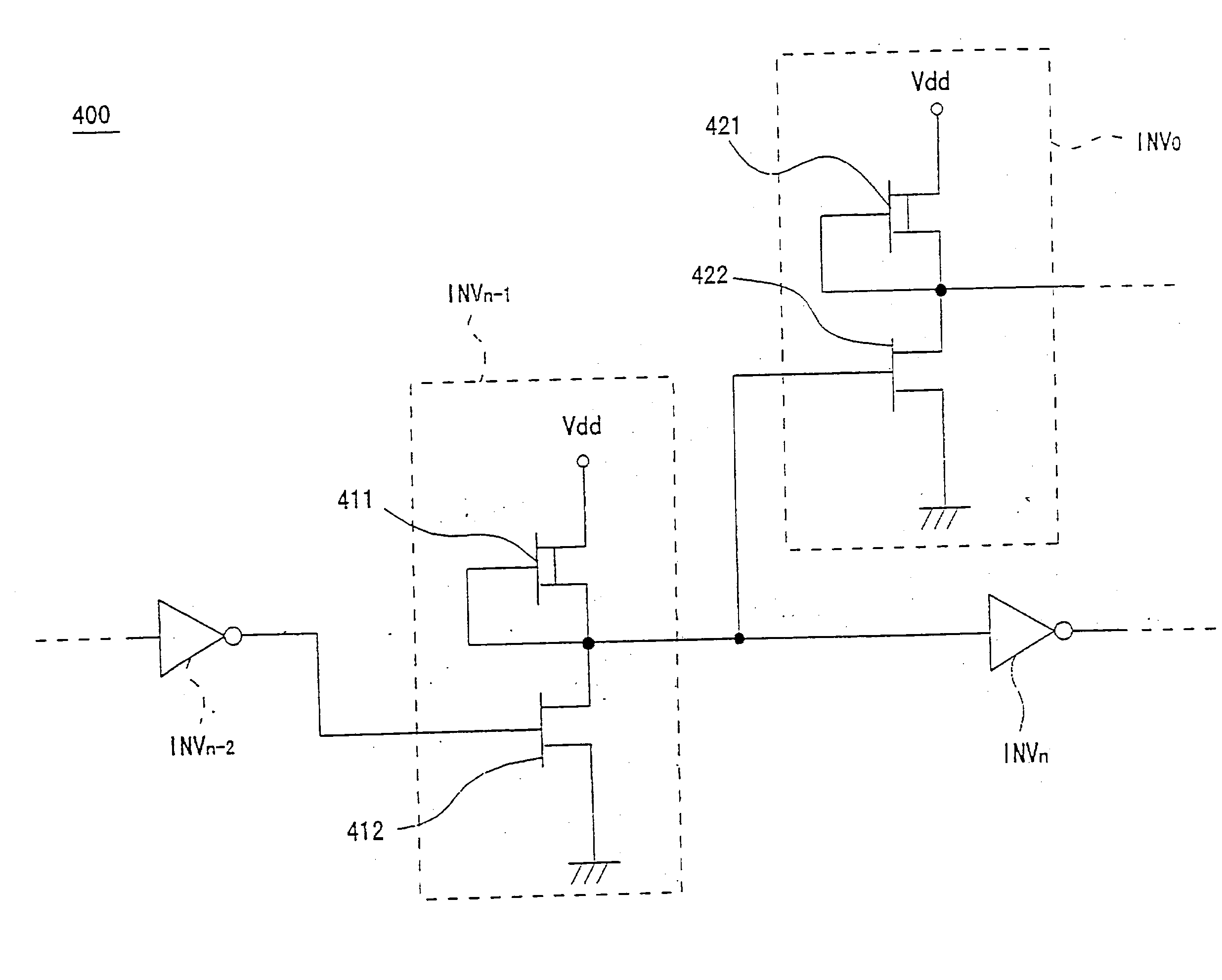
[0040] A limiting amplifier with a power detection circuit according to the second embodiment of the invention will be described with reference to FIG. 4.
[0041] FIG. 4 shows circuit diagram of a current-voltage conversion circuit 400 according to the second embodiment. In FIG. 4, the same reference numbers are used for the same elements as used in FIG. 1.
[0042] In the limiting amplifier with a power detection circuit according to the second embodiment, the logical threshold of the detection inverter INV.sub.0 is made lower than that of the amplification inverter INV.sub.n-1, which is different from the limiting amplifier with a power detection circuit 100 according to the first embodiment.
[0043] In FIG. 4, the (n-1)th amplification inverter INV.sub.n-1 is provided with a depression type FET 411 and an enhancement type FET 412. The detection inverter INV.sub.0 is provided with a depression type FET 421 and an enhancement type FET 422. The connection method between the FETs 411 and 41...
PUM
 Abstract
Description
Claims
Application Information