6-Mirror projection objective with few lenses

Inactive Publication Date: 2003-12-25
CARL ZEISS SMT GMBH
View PDF5 Cites 44 Cited by
  • Summary
  • Abstract
  • Description
  • Claims
  • Application Information

AI Technical Summary

Problems solved by technology

A drawback of this embodiment with few lenses is, that the image-side numerical aperture NA is equal to 0.6, and the refractive optical elements have large diameters, which is undesirable with respect to availability of materials and costs, as well as manufacturing feasibility.
I

Method used


Image

  • 6-Mirror projection objective with few lenses
  • 6-Mirror projection objective with few lenses
  • 6-Mirror projection objective with few lenses

Examples


Embodiment Construction

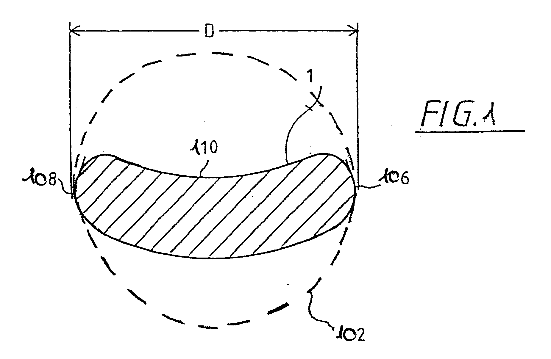
[0028] FIG. 1 illustrates what is meant in the present application by the off axis segment and the diameter of the off axis segment.

[0029] FIG. 1 by way of example shows a kidney-shaped field for a kidney-shaped illuminated field 1 on a reflective or refractive element of the projection objective. Such a shape for the off axis segment is expected when using the objective according to the invention in a microlithography projection exposure apparatus when the object plane is illuminated with a segment of an annular field. The circular envelope 102 fully encloses the kidney shape and coincides at two points 106, 108, with the edge 110 of the kidney shape. The circular envelope is always the smallest circle that encloses the off axis segment. The diameter D of the off axis segment is then found from the diameter of the circular envelope 102.

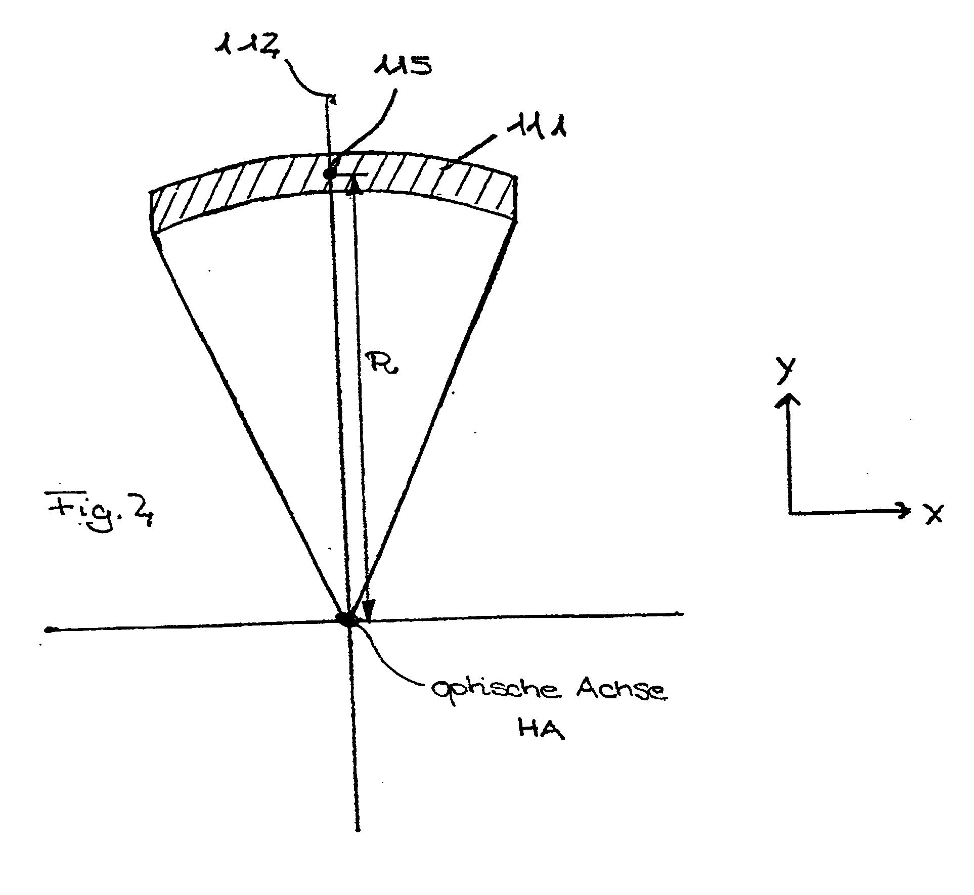
[0030] FIG. 2 illustrates the object field 111 of a projection exposure apparatus in the object plane of the projection objective that is imaged usi...


PUM


Abstract

There is provided a projection objective for wavelengths of <=193 nm for imaging an object field in an object plane into an image field, in an image plane. The projection objective includes a first reflective optical element, a second reflective optical element, a third reflective optical element, a fourth reflective optical element, a fifth reflective optical element, and a sixth reflective optical element, and a refractive optical element. The reflective and refractive optical elements each have an off axis segment with a diameter. The projection objective has an image-side numerical aperture >=0.65, and the off axis segment of the refractive optical element has a diameter that is less than 1/3<rd >of the distance from the object plane to the image plane.

Description

[0001] The present application is claiming priority of U.S. Provisional Patent Application Serial No. 60 / 368,180, filed on Mar. 28, 2002.[0002] 1. Field of the Invention[0003] This invention relates to a projection objective for short wavelengths, preferably of .ltoreq.193 nm, especially .ltoreq.157 nm, and also to a projection exposure apparatus and a chip production, each of which employs such a projection objective.[0004] 2. Description of the Related Art[0005] Lithography with wavelengths of <193 nm is discussed as a possible technique for imaging structures of <130 nm and with special preference <100 nm. The resolution of a lithographic system is described by the following equation:RES=k.sub.1.multidot.(.lambda. / NA)[0006] wherein k.sub.1 is a specific parameter of the lithographic process, .lambda. is the wavelength of the incident light, and NA is the numerical aperture of the system on the image side.[0007] For imaging systems in the wavelength region of <193 nm, ...

Claims


Application Information

Patent Timeline
IPC IPC(8): G02B17/08
CPCG02B17/0844G03F7/70225G02B17/0892
Inventor SHAFER, DAVID R.
Owner CARL ZEISS SMT GMBH
Why Eureka
Try Eureka