Eureka AIR delivers breakthrough ideas for toughest innovation challenges, trusted by R&D personnel around the world.

Method and device for producing ground resin particles

a technology of ground resin and resin particles, which is applied in the direction of solid separation, grain milling, gas current separation, etc., can solve the problems of reduced grinding ability, reduced apparent density of obtained ground particles, and reduced grinding ability of ground resin particles or non-classified coarse resin particles. excellent

Inactive Publication Date: 2004-01-22
DAIKIN IND LTD
View PDF5 Cites 5 Cited by
  • Summary
  • Abstract
  • Description
  • Claims
  • Application Information

AI Technical Summary

Benefits of technology

[0014] As for the resin particles to be ground, at least one kind of resin particles is used, and a particularly excellent effect can be obtained when at least one kind of resin particles is fluorine resin particles.

Problems solved by technology

However, when fluorine resin particles are ground according to the impact grinding method, the obtained ground particles have small apparent density, become fibrous and have inferior properties owing to the heat generation during the grinding process.
However, when fluorine resin particles or other types of resin particles are ground according to the grinding method using a conventional jet mill, the ground resin particles or non-classified coarse resin particles tend to become adhesive and agglomerate.
The fallen particles sometimes remain in a bulk at the bottom of the grinding chamber, resulting in the reduction of grinding ability (amount of collected resin particles of an intended particle size).
In this way, conventional jet mills have a disadvantage that the grinding ability is extremely low when compared with the impact grinding method.
In addition, when the temperature of the resin particles to be ground, the compressed air or the jet mill is high, the resin particles tend to have large elasticity and the grinding of the particles becomes difficult, resulting in the lowering of the grinding efficiency.

Method used


Image

  • Method and device for producing ground resin particles
  • Method and device for producing ground resin particles
  • Method and device for producing ground resin particles

Examples


examples 5 to 9

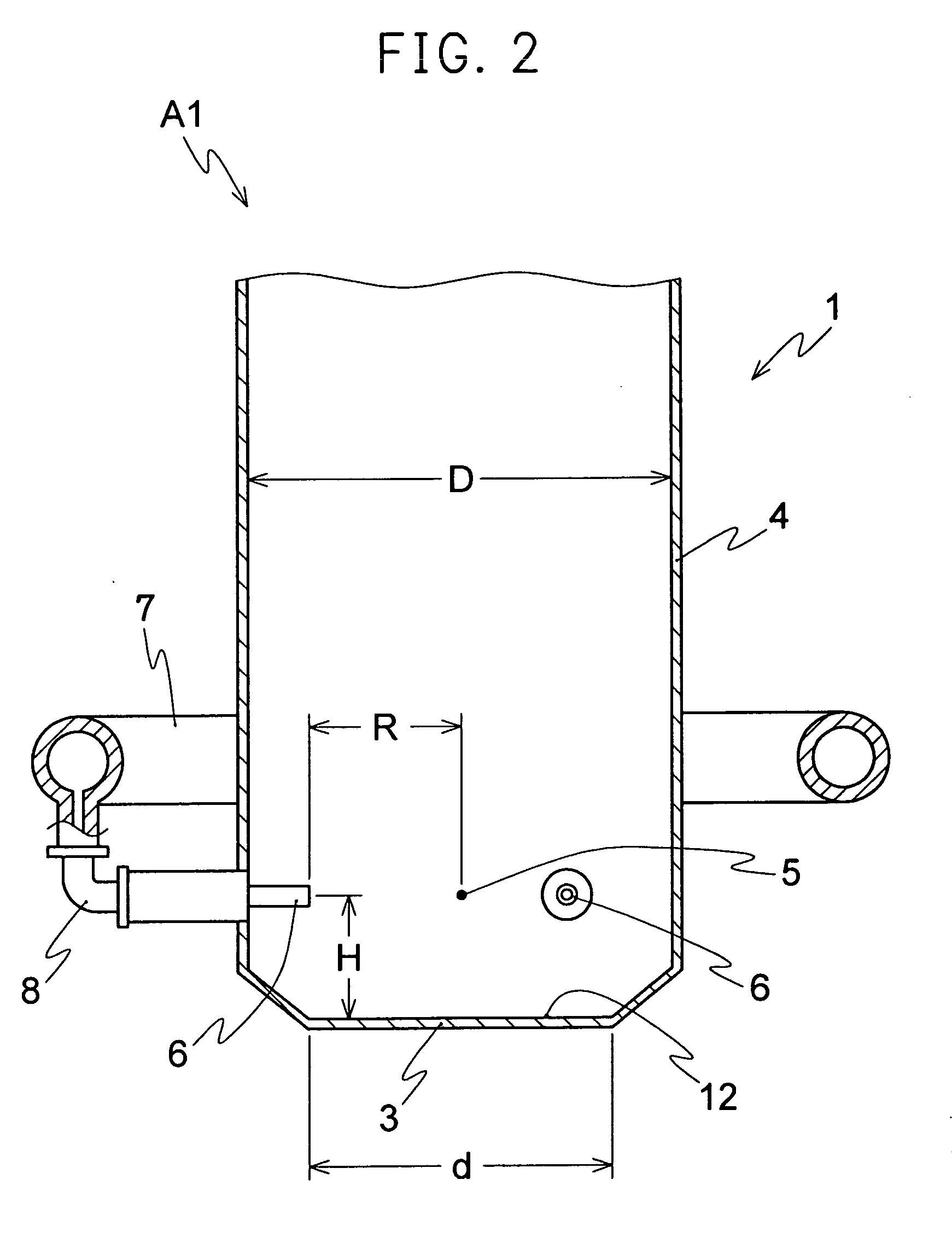
[0094] In order to confirm whether the height of the injection point influences the flowability of the powder, PTFE dried powder (water content: 0.01% by weight) was ground according to the grinding condition shown in Table 3, and the relationship between the nozzle distance of jet nozzles and the height, which influences the grinding ability was examined. The compressed air was cooled to 5.5.degree. C. and supplied to maintain the jet mill to 6.0 to 9.0.degree. C. The rotation number of the classifying rotor for collection was set to 1,200 rpm. The results are shown in Table 4 and FIG. 7.

3TABLE 3 Grinding condition Diameter of barrel (inner diameter) (mm) 440 Air pressure (MPa) 0.9 Supplied amount of material (kg / hr) 350 Average particle diameter of material (.mu.m) 700

[0095]

4 TABLE 4 Height of Ex. 5 Ex. 6 Ex. 7 Ex. 8 Ex. 9 injection point Circle diameter (mm) (mm) 300 350 372 400 400 Grinding ability 90 234.8 295.6 291.6 311.2 --(kg / hr) 58 -- -- -- -- 346.2

[0096] Table 4 and FIG. ...

example 10

[0099] PTFE resin particles (average particle size: 700 .mu.m) after suspension polymerization which were associated with 6% by weight of water (water: PTFE=6:94) were supplied as PTFE resin particles in Example 1, at a speed of 25.5 kg / hr. On the other hand, the compressed air was injected to the mill at 17.5.degree. C. under a pressure of 0.92 MPa. The cooling of the jet mill was not carried out. As a result, the inside temperature of the mill was maintained at 5.7.degree. C.

[0100] The collected ground PTFE powder had an average diameter of 17.9 .mu.m, an apparent density of 0.26 g / cm.sup.3 and a water content of 0.07% by weight. The grinding efficiency was 34.0 kg / hr.

examples 11 to 13

[0101] The grinding of water-containing PTFE powder (water content: 6% by weight) was carried out in the same manner as in Example 10 except that the temperature of the compressed air was changed to 20.9.degree. C. (Example 11), 32.2.degree. C. (Example 12) and 42.0.degree. C. (Example 13). The results are shown in Table 5.

5 TABLE 5 Ex. 10 Ex. 11 Ex. 12 Ex. 13 Temperature of compressed air 17.5 20.9 32.2 42.0 supplied (.degree. C.) Temperature to be maintained 5.7 9.8 17.1 22.7 in jet mill (.degree. C.) Grinding ability (kg / hr) 34.0 34.5 32.0 32.4 Properties of collected ground resin particle Average particle size (.mu.m) 17.9 16.7 17.5 17.8 Apparent density (g / cm.sup.3) 0.26 0.27 0.26 0.27 Water content (% by weight) 0.070 0.073 0.005 0.004

[0102] Table 5 shows that when water is associated with the resin particles to be ground, the temperature inside the jet mill can be remarkably lowered and cooling of the jet mill is not needed. In addition, even if the temperature of the compres...


PUM


Abstract

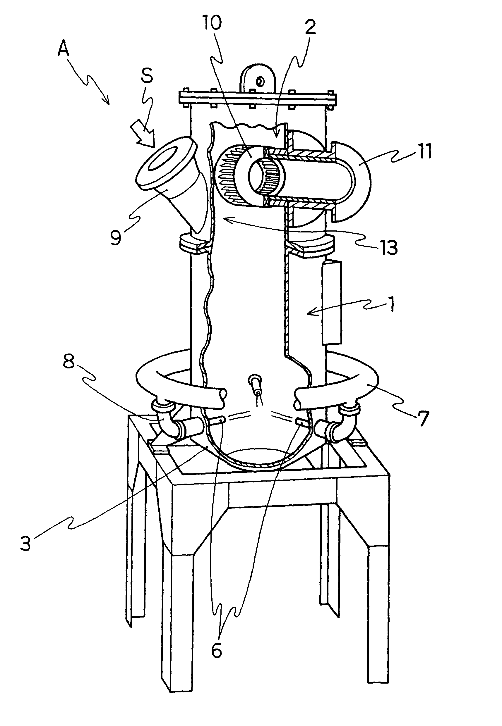
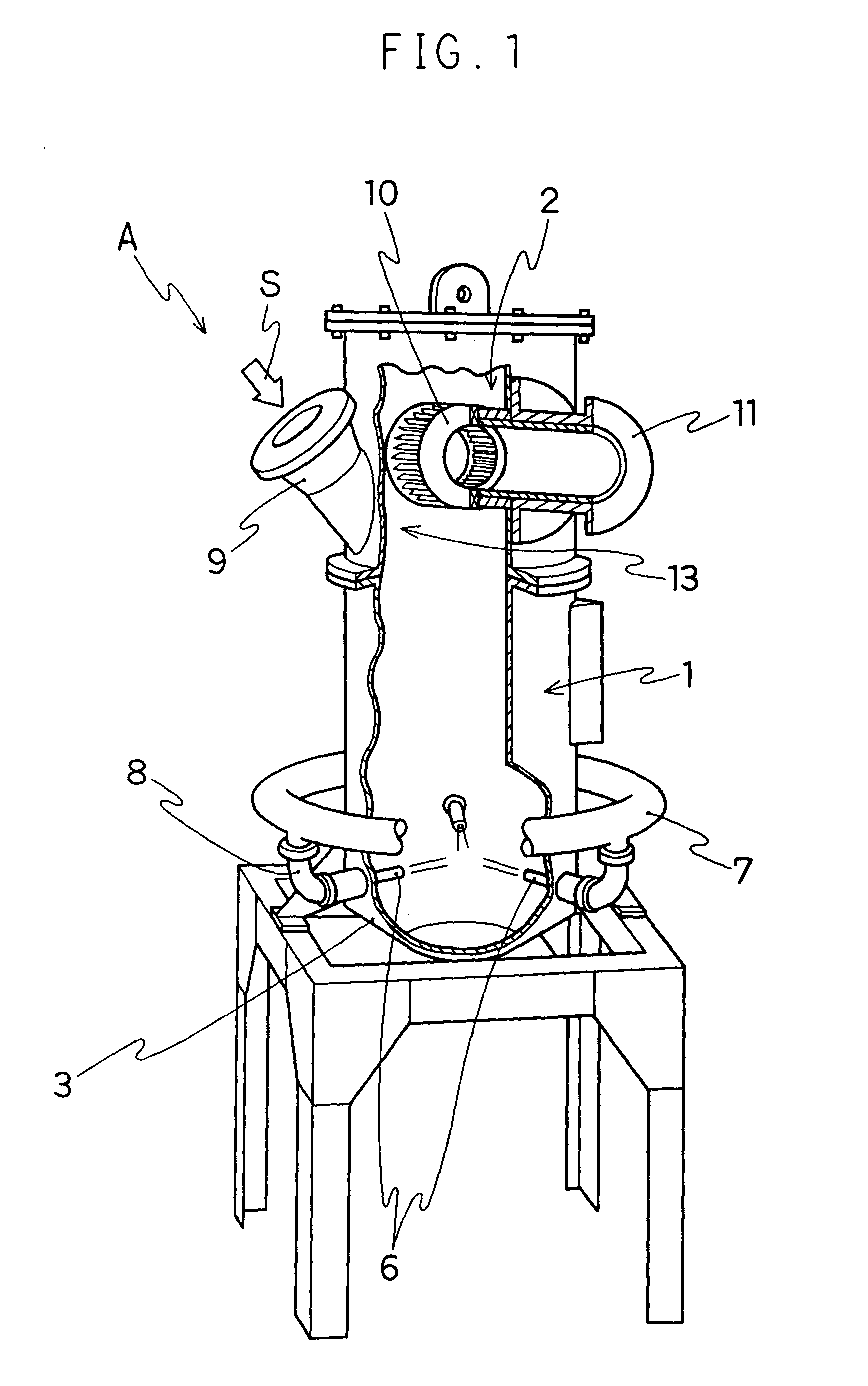
A process for preparing ground resin particles is provided by modifying a jet mill with opposed fluidized bed, wherein the grinding efficiency can be dramatically increased, the operating conditions can be relieved, and smaller device size and reduced running cost can be achieved. By using a jet mill having a plurality of jet nozzles disposed at predetermined positions in a barrel of a grinding chamber toward the injection point of the grinding chamber and a bottom wall having a flat surface in part or in whole, parallel to the jet nozzles, or a jet mill having a plurality of jet nozzles disposed at predetermined positions in a barrel of a grinding chamber toward the injection point of the grinding chamber and a bottom wall having a conical projection immediately below the injection point, resin particles to be ground are jetted with or without water, thereby being ground to obtain ground resin particles of an intended particle size.

Description

[0001] The present invention relates to a process for preparing resin particles by using a jet mill. According to the present invention, resin particles difficult to produce efficiently into uniform ground particles, such as fluorine resin particles, polytetrafluoroethylene (PTFE) particles in particular, can be ground into uniform particles in an efficient manner. The present invention also relates to a process in which cooling is not carried out in the grinding step, thereby achieving the reduction of production costs. Further, the present invention relates to a jet mill suitable for such process.[0002] Various methods are known as a grinding method of resin particles, particularly, fluorine resin particles. Among them, the impact grinding method with a pneumatic classifier is widely employed since the method is economically efficient in preparing resin particles of a relatively large particle size. However, when fluorine resin particles are ground according to the impact grinding...

Claims


Application Information

Patent Timeline
IPC IPC(8): B02C19/06
CPCB02C19/068
Inventor SAWADA, YASUHIKOTANAKA, TOSHINARISHIMADA, KAZUHIKO
Owner DAIKIN IND LTD
Why Eureka
Eureka Blog
Learn More