Single-event upset immune frequency divider circuit

a frequency divider circuit and single-event technology, applied in pulse manipulation, pulse technique, instruments, etc., can solve the problems of phase shift in output signals, runt pulses on clock paths,

Inactive Publication Date: 2004-01-29
BAE SYST INFORMATION & ELECTRONICS SYST INTERGRATION INC
View PDF0 Cites 7 Cited by
  • Summary
  • Abstract
  • Description
  • Claims
  • Application Information

AI Technical Summary

Problems solved by technology

One problem with prior art frequency divider circuits, such as frequency divider circuit 10, is that they are very susceptible to single-event upsets (SEUs) or single-event transients (SETs) that can result in runt pulses occurred on the clock path and subsequently phase shifts in the output signals.

Method used


Image

  • Single-event upset immune frequency divider circuit
  • Single-event upset immune frequency divider circuit
  • Single-event upset immune frequency divider circuit

Examples


Embodiment Construction

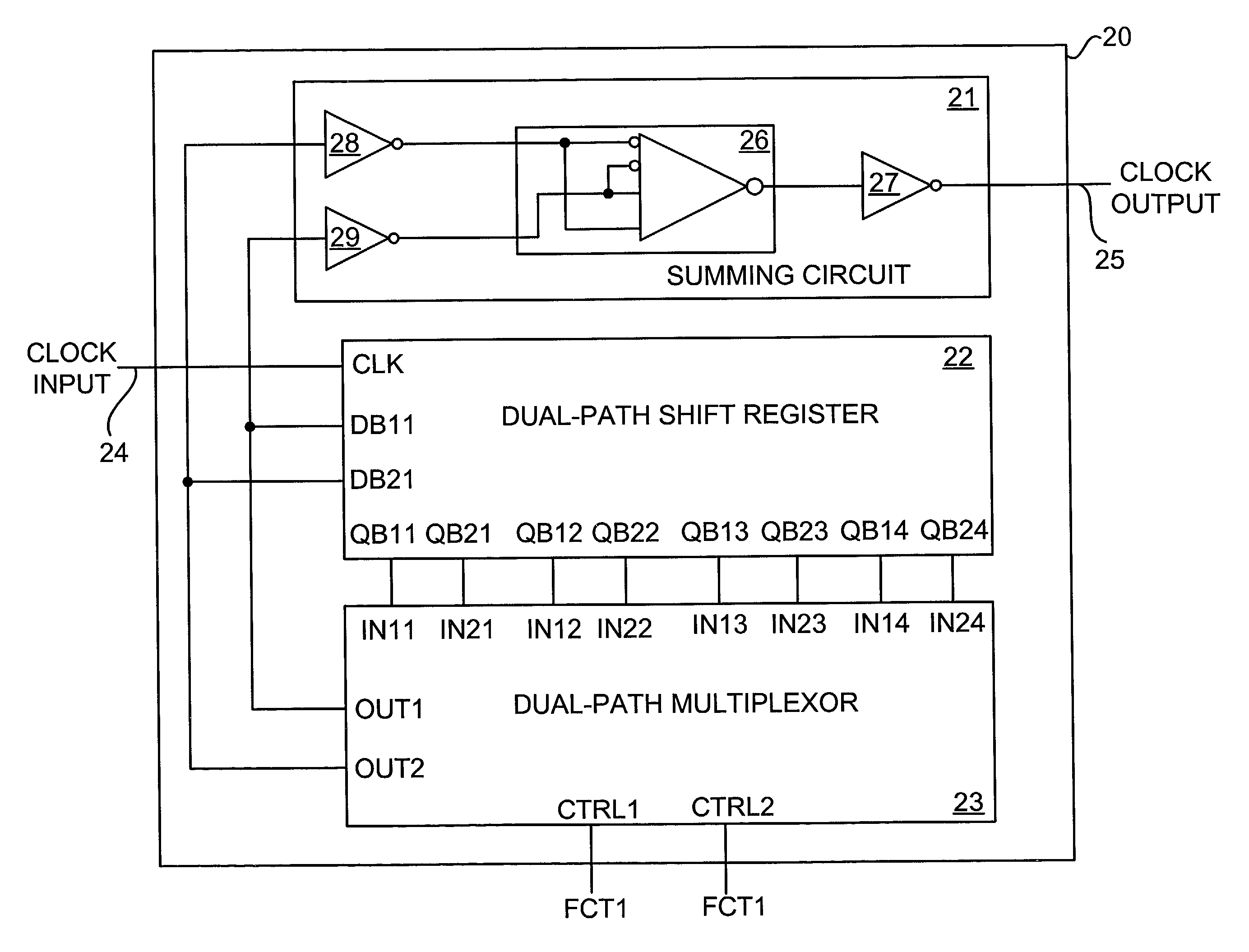
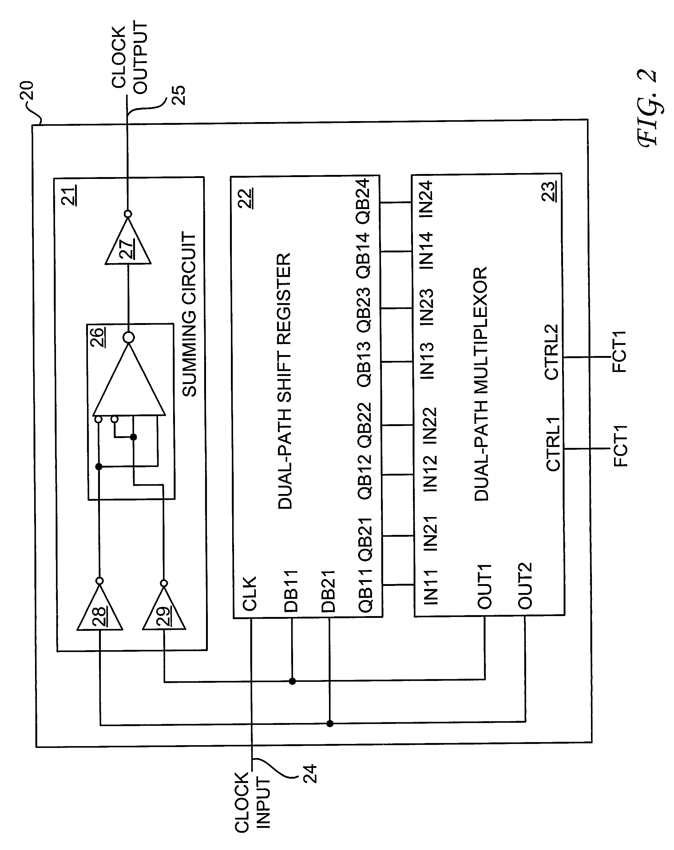
[0018] With reference now to FIG. 2, there is depicted a block diagram of a single-event upset (SEU) immune frequency divider circuit, in accordance with the preferred embodiment of the present invention. As shown, an SEU immune frequency divider circuit 20 includes a summing circuit 21, a dual-path shift register 22 and a dual-path multiplexor 23. SEU immune frequency divider circuit 20 also includes a clock input 24 and a clock output 25. Dual-path shift register 22 includes four output pairs, namely, QB11-QB21, QB12-QB22, QB13-QB23 and QB14-QB24. Dual-path multiplexor 23 may select any one of the four output pairs of dual-path shift register 22 to be fed back to an input pair DB11-DB12 of dual-path shift register 22. Depending on the selected output pair to be fed back, SEU immune frequency divider circuit 20 may divide an input clock signal from, for example, a system clock at clock input 24 by 2, 4, or 8 times in order to produce an output clock signal that is one-half, one-fou...


PUM


Abstract

A single-event upset immune frequency divider circuit is disclosed. The single-event upset immune frequency divider circuit includes a dual-path shift register, a dual-path multiplexor, and a summing circuit. The dual-path shift register has a clock input, one signal input pair and multiple signal output pairs. The dual-path multiplexor has multiple signal input pairs and one output pair. The signal input pairs of the dual-path multiplexor are respectively connected to the signal output pairs of the dual-input shift register. The dual-path multiplexor selects one of the signal output pairs of the dual-path shift register for feeding back into the signal input pair of the dual-path shift register. The summing circuit then sums the signal input pair of the dual-path shift register to generate an output clock signal that is a fraction of the frequency of an input clock signal at the clock input of the dual-path shift register.

Description

RELATED PATENT APPLICATION[0001] The present patent application is related to a copending application U.S. Ser. No. 09 / ___,___ filed on even date, entitled "SINGLE-EVENT UPSET IMMUNE FLIP-FLOP CIRCUIT" (Attorney Docket No. BA-00578).[0002] 1. Technical Field[0003] The present invention relates to electronic circuits in general, and in particular to frequency divider circuits. Still more particularly, the present invention relates to a single-event upset immune frequency divider circuit.[0004] 2. Description of the Related Art[0005] Frequency divider circuits are commonly used in electronic devices that include counting circuits, phase-locked loop circuits, and / or frequency synthesizer circuits. Generally speaking, frequency dividers are used to generate signals of relatively lower frequencies by dividing a high frequency signal already existed within an electronic system. For example, if a 50 MHz signal is desired from a 100 MHz clock signal existed within an electronic system, a fr...

Claims


Application Information

Patent Timeline
Patent Type & Authority Applications(United States)
IPC IPC(8): H03K5/15H03K19/003H03K21/40
CPCH03K5/15093H03K21/40H03K19/0033
Inventor WOOD, NEIL E.
Owner BAE SYST INFORMATION & ELECTRONICS SYST INTERGRATION INC
Why Eureka
Try Eureka