Eureka AIR delivers breakthrough ideas for toughest innovation challenges, trusted by R&D personnel around the world.

Stop valve

Active Publication Date: 2004-02-05
BRASSCRAFT MFG CO
View PDF35 Cites 70 Cited by
  • Summary
  • Abstract
  • Description
  • Claims
  • Application Information

AI Technical Summary

Benefits of technology

[0010] The closed end wall of the control sleeve has a hard plastic handle engaging stem section axially extending therefrom. The handle engaging stem section includes a geometric shape which mates with the handle. The handle stop rotation can be attained by either a corresponding geometric shape in the body or a protrusion from the body that mates with an integral feature of the handle. Desirably, the handle has a first annular section with internal geometric cross section that mates with the hard plastic section of the control sleeve. The handle is secured to the control sleeve by either using a fastener or mating the handle with a protrusion on the rigid stem.
[0011] In accordance with a preferred embodiment of the stop valve, the rigid valve stem facilitates the application of sufficient torque to break the binding forces sometimes found in such valves. Further, the softer material used to mold the control sleeve provides a sealing resilience to prevent fluid leakage past the control sleeve. The multishot molding process allows the valve stem to be molded to the previously molded control sleeve. Additional molding steps can be used to mold a locking retainer to the valve member and seal members which amount to integral O-ring seals.

Problems solved by technology

Prior inventions containing a single plastic control sleeve could not provide sufficient performance under all water conditions.

Method used


Image

  • Stop valve
  • Stop valve
  • Stop valve

Examples


Embodiment Construction

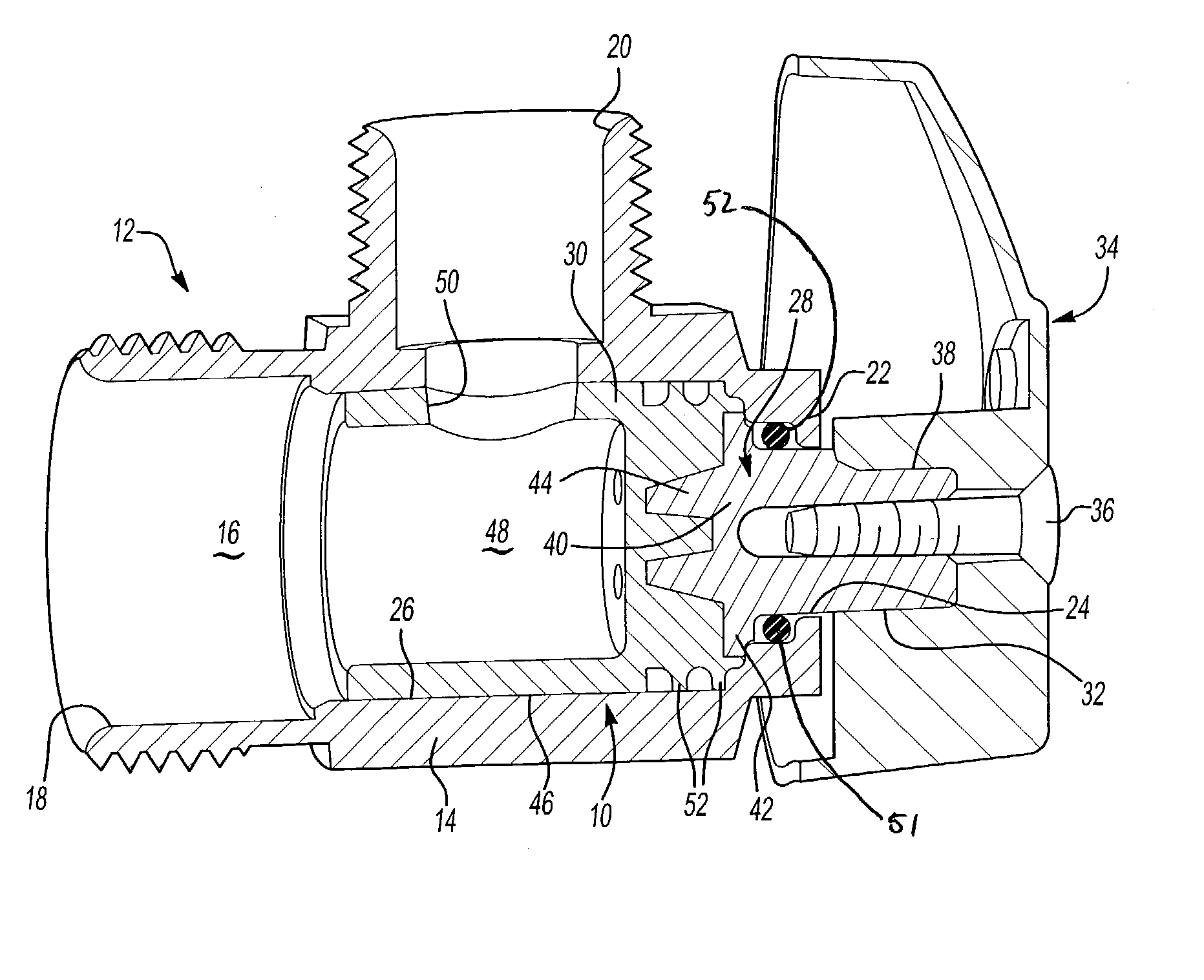
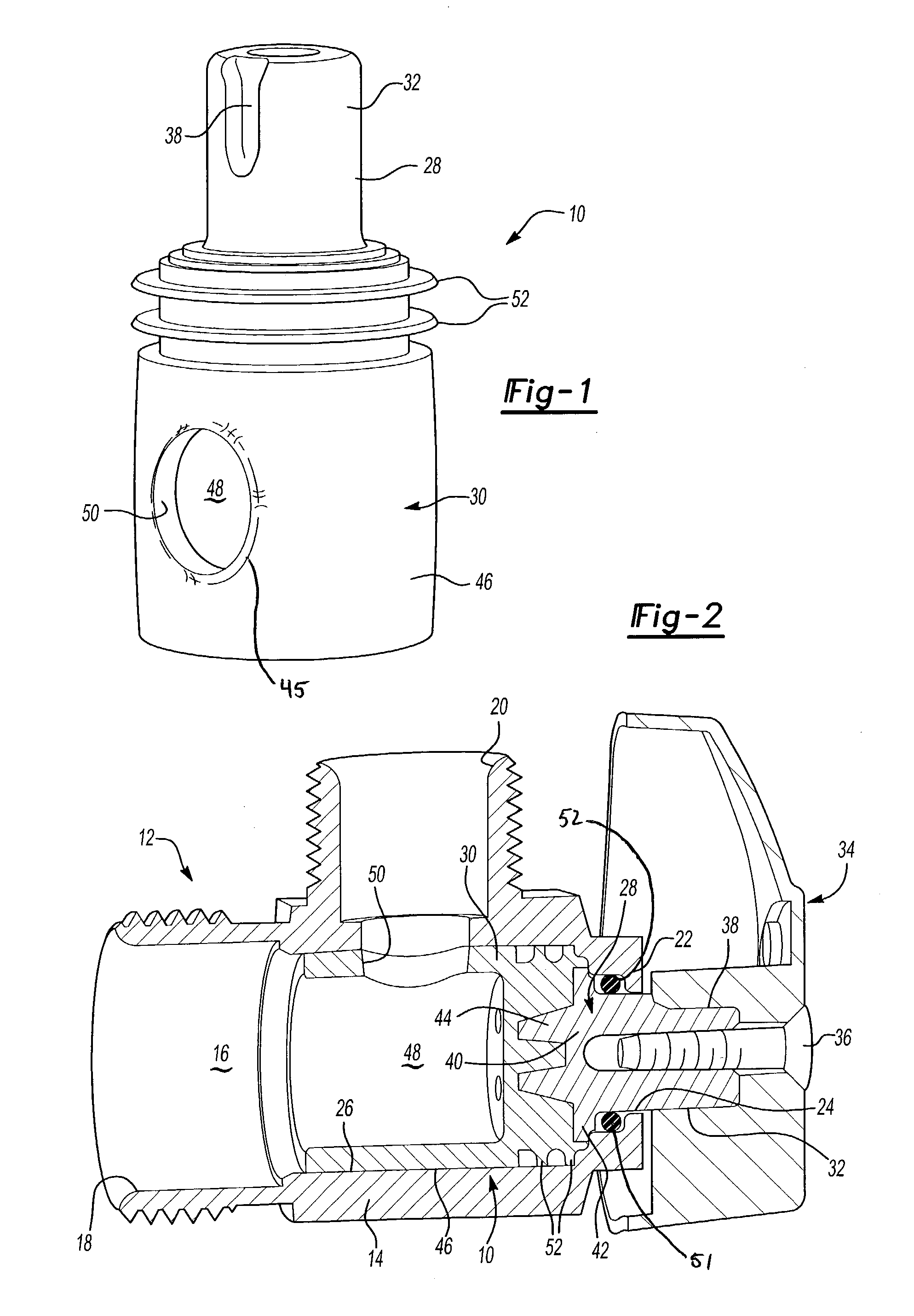
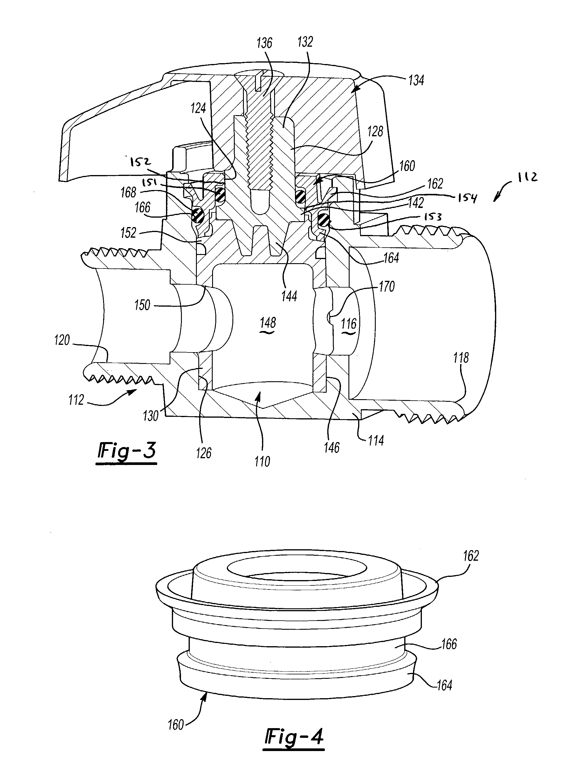
[0022] Referring first to FIGS. 1 and 2, there is shown a valve member 10 manufactured in accordance with the present invention and designed to control the flow of fluid through a valve 12. As will be subsequently described, the valve member 10 is manufactured with sufficient strength and rigidity to withstand the torque associated with manipulation of the valve member 10 and with sufficient pliability and resiliency to prevent fluid leakage. These dual material properties provide an efficient and effective means of controlling fluid flow through the valve 12. The valve member 10 of the present invention will be described in conjunction with an angled valve (FIG. 2) and a straight valve (FIG. 3). The operation and properties of the valve member 10 are similar for both types of valves.

[0023] The valve 12 includes a valve body 14 having a housing chamber 16 for receiving the valve member 10. The valve body 14 includes an inlet 18 preferably connected to a fluid source and an outlet 20...


PUM


Abstract

A stop valve includes a valve body, a multi shot resilient control sleeve, O-ring and handle. The control sleeve is molded to the valve stem to create an integral but separately molded fluid control member. Inlet line pressure resiliently biases the side walls of the control sleeve and a circumferential sealing flap formed thereon into sealing engagement with the valve bore to prevent leakage. The control sleeve consists of a hard plastic cylinder and a flexible barrel member molded as one consistent piece by a multishot molding process. The O-ring also serves as a backup seal to prevent leakage to atmosphere. A valve handle is secured to the valve by either a screw or a snap protrusion.

Description

[0001] This application claims priority from U.S. Provisional Application No. 60 / 400,280 filed on Jul. 31, 2002.[0002] 1. Field of the Invention[0003] A stop valve for controlling the flow of fluid through fluid lines and, in particular, to a stop valve manufactured through a multi-stage molding process to include a sealingly resilient fluid control sleeve and a more rigid valve stem for rotation of the sleeve.[0004] 2. Description of the Prior Art[0005] A stop valve is a shut-off valve to permit the replacement of washers or other repairs to be accomplished on a plumbing fixture without shutting down an entire plumbing system. The stop valve is commonly located in the fixture supply line between a wall and the fixture. Stop valves are generally available in two basic styles. One style is known as an angle stop valve that has the inlet and outlet of the valve at right angles to each other. The other standard configuration is a straight-through arrangement wherein the inlet and outle...

Claims


Application Information

Patent Timeline
IPC IPC(8): F16K5/04
CPCF16K5/0414
Inventor TURNAU III, WILLIAM F.ALLSTEAD, BRADLEY E.TOKARZ, STEVEN J.
Owner BRASSCRAFT MFG CO
Why Eureka
Eureka Blog
Learn More