System and method for mass flow detection device calibration

a detection device and mass flow technology, applied in the field of measurement devices, can solve the problems of corrosive gasses, large number of gasses, and inability to calibrate an mfc with all of these gasses

Inactive Publication Date: 2004-02-12
BROOKS INSTRUMENT
View PDF20 Cites 19 Cited by
  • Summary
  • Abstract
  • Description
  • Claims
  • Application Information

AI Technical Summary

Problems solved by technology

It would be impractical to calibrate an MFC with all of these gasses for a number of reasons.
For one thing, the sheer number of gasses is very large.
This problem is compounded by the fact that a manufacturer may have several different types of MFCs, each of which would have to be calibrated with each of the gasses.
Another problem is that some of the gasses are corrosive, so it is preferable not to use them to calibrate the MFC.
Over the years, the accuracy of particular gas correction factors has occasionally been challenged.
Even though the accuracy of the gas correction factors may be periodically re-confirmed, the overall accuracy of the measurement devices is still limited by the assumption of linearity.
If the flow through the sensor is larger than 2 sccm, significant nonlinearities may exist.
The non-linearity is due to the fact that the gas does not fully thermally develop within the MFC sensor.
Gases with a low thermal conductivity to heat capacity ratio will have difficulty achieving fully developed thermal profiles.
Thus, while 1% error may be typical, there will be many MFCs that have error exceeding 1%.
Some of the devices will substantially exceed this typical error.
To date, the industry has not been able to conquer this problem, and the attainable accuracy with process gases has been limited to greater than 1% of reading.
While this technique can compensate for basic differences in fluid properties and achieve better accuracies than more simple models (e.g. simple corrections for different heat capacities), it does not address one of the fundamental limitation faced by most flow instrumentation: how to adjust for device-to-device differences which are related to parts tolerancing or manufacturing processes in order to achieve the same performance in the "end products."
The prior art provides no means to compensate for device design and variations within the tolerances of the design.
In fact, since prior art devices were typically analog, they did not even provide means to store device information or convert this information into correction factors to compensate for resulting measurement differences.

Method used


Image

  • System and method for mass flow detection device calibration
  • System and method for mass flow detection device calibration
  • System and method for mass flow detection device calibration

Examples


Embodiment Construction

[0033] A preferred embodiment of the invention is described below. It should be noted that this and any other embodiments described below are exemplary and are intended to be illustrative of the invention rather than limiting.

[0034] Broadly speaking, the invention comprises systems and methods for improving the accuracy of mass flow controllers (MFCs) using device-specific information.

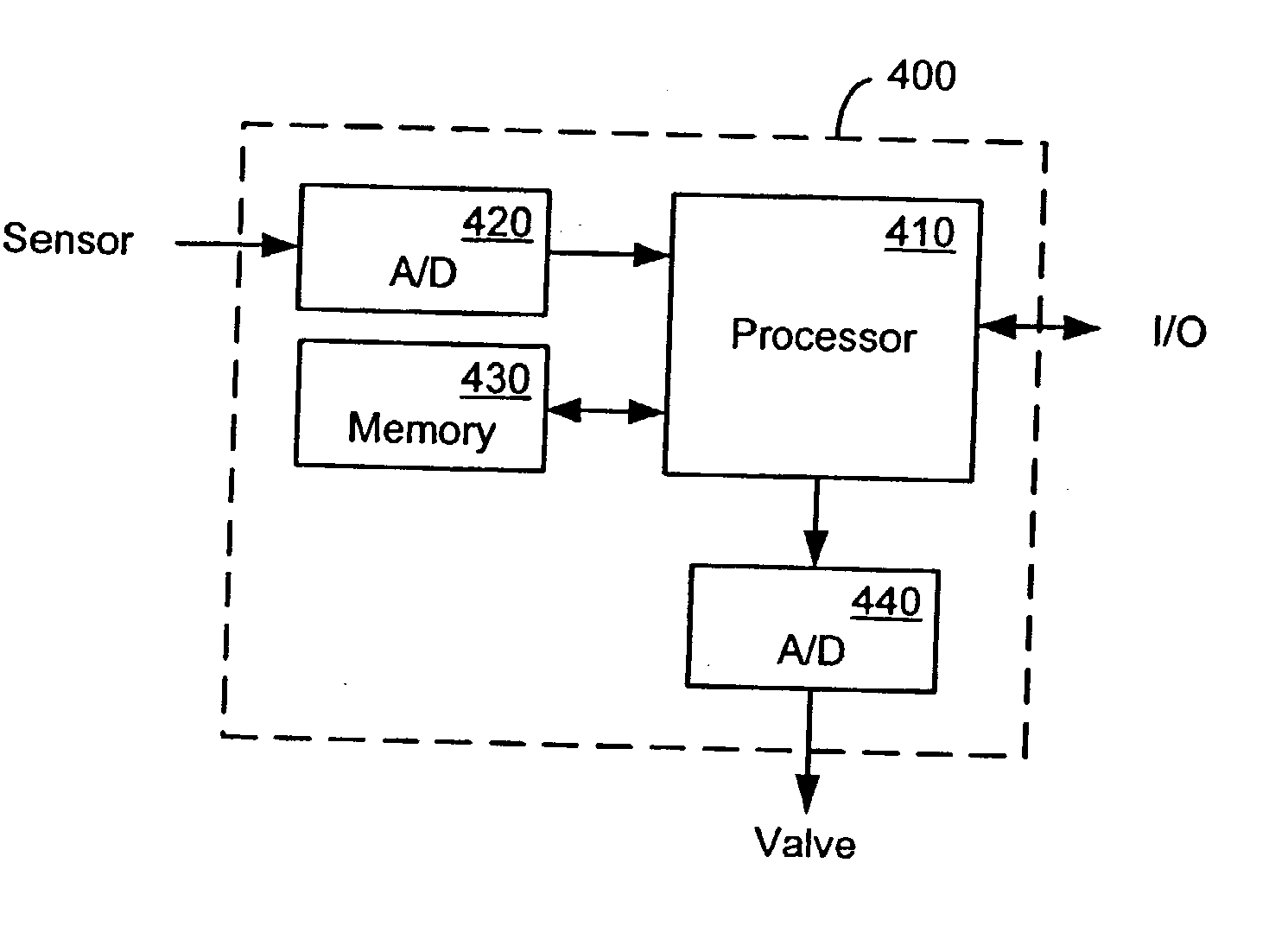
[0035] In one embodiment, a thermal MFC is calibrated with a first (calibration) gas for use with a second (process) gas. The flow of the process gas sensed by the MFC is corrected using a gas correction factor that accounts for the differences between the calibration gas and the process gas. The sensed flow is also corrected using one or more device-specific correction factors. One of the device-specific factors is based on the resistance of the flow sensor, and another of these factors is based on the split flow ratio of the MFC. Data corresponding to the correction factors is stored in a memory with...


PUM

PropertyMeasurementUnit
sensor resistanceaaaaaaaaaa
resistanceaaaaaaaaaa
mass flowaaaaaaaaaa

Abstract

Systems and methods for correcting measurements of fluid flow using device-specific information to compensate for differences between individual devices of the same design. In one embodiment, a method comprises providing device-specific calibration data; sensing a fluid flow; computing a measured fluid flow based on the sensed fluid flow, and correcting the measured fluid flow based on the device-specific calibration data. More particularly, the fluid flow measurement is corrected using correction factors that compensate for the use of a gas that is different from the calibration gas (CF0(1+aF+bF<2>+cF<3>)), for device variations in sensor sensitivity (1+alphaDeltaR), and for variations in the split flow of fluid through the flow meter (1-betaDeltaADC(Sp/100)<2>). The sensor and split flow correction factors may be used independently of each other in some embodiments.

Description

[0001] 1. Technical Field[0002] The invention relates generally to measurement devices and more particularly to systems and methods for improving the accuracy of mass flow measurement and resulting control of fluids by correcting for physical differences between similar measurement devices.[0003] 2. Related Art[0004] Thermal mass flow controllers ("MFCs") measure the flow of a gas by sensing a temperature difference upstream and downstream of a heated section of capillary tubing through which the gas flows. The temperature difference between the upstream and downstream sensors is directly proportional (to the first order) to the gas' specific heat, or heat capacity, and the gas flow.[0005] Thermal MFCs are typically calibrated with one gas and used with another, different gas. A different calibration gas is used because there are approximately 200 pure gasses and 300 mixtures that are used in the semiconductor industry. It would be impractical to calibrate an MFC with all of these g...

Claims


Application Information

Patent Timeline
Patent Type & Authority Applications(United States)
IPC IPC(8): C01B17/22G01F1/12G01F1/48G01F1/50G01F1/68G01F1/684G01F1/00G01F1/696G01F5/00G01F25/00G01L27/00G06F19/00
CPCG01F1/684G01F1/6842G01F25/0007G01F5/00G01F1/6965Y10T137/7761G01F25/10
Inventor TISON, STUART A.LU, SHILIANG
Owner BROOKS INSTRUMENT
Why Eureka
Try Eureka