
Method and system for storing memory compressed data onto memory compressed disks

Active Publication Date: 2004-02-12
IBM CORP
View PDF9 Cites 73 Cited by
  • Summary
  • Abstract
  • Description
  • Claims
  • Application Information

AI Technical Summary

Benefits of technology

[0046] With the unique and unobvious aspects of the present invention, a method (and system) are provided for storing memory-compressed data directly to disk.
[0047] Further, the invention results in reduced latency in I / O operations. Indeed, the data can be transferred to and from disk without having to be buffered while waiting for compression / decompression.
[0048] Further, reduced resource consumption occurs at the disk adapter. That is, the data does not need to be buffered while waiting for compression / decompression, and there is no need to manage the queue of pages waiting to be compressed / decompressed, etc.
[0049] Additionally, increased bandwidth is possible between main memory and disk, by a factor equal to the compression ratio in main memory.
[0050] Furthermore, better algorithms are provided for data placement on disk. That is, since the size of the compressed data is known, better storage decisions can be made about how to place the compressed data on disk
[0051] Additionally, with the invention, a compressed disk can be used as a paging system for a compressed memory system. That is, in a compressed memory system without compressed secondary store, pages swapped to disk by the operating system are decompressed while the I / O operation is executed.
[0052] Further, the present invention does not rely on specific features of the compressed disk organization, and can be used with any existing compressed disk scheme. Indeed, the invention can be used by existing hardware systems (e.g., the exemplary hardware systems of FIGS. 1 and 4) and does not require any substantial modification to the existing hardware.

Problems solved by technology

Another problem arises in disk systems in going from the disk to the main memory and trying to individually access compressed pages on the disk as opposed to accessing compressed data in the main memory.
Since the structures that have been created to support memory compression and disk compression are quite different, some inefficiencies arise when a system supporting memory compression operates with a compressed disk.
However, transmitting such compressed data directly to disk without additional and costly steps of decompression and recompression requires changes to the I / O operations and the system structure.

Method used


Image

  • Method and system for storing memory compressed data onto memory compressed disks
  • Method and system for storing memory compressed data onto memory compressed disks
  • Method and system for storing memory compressed data onto memory compressed disks

Examples


Embodiment Construction

[0061] Referring now to the drawings, and more particularly to FIGS. 1-7, there are shown preferred embodiments of the method and structures according to the present invention.

[0062] PREFERRED EMBODIMENT

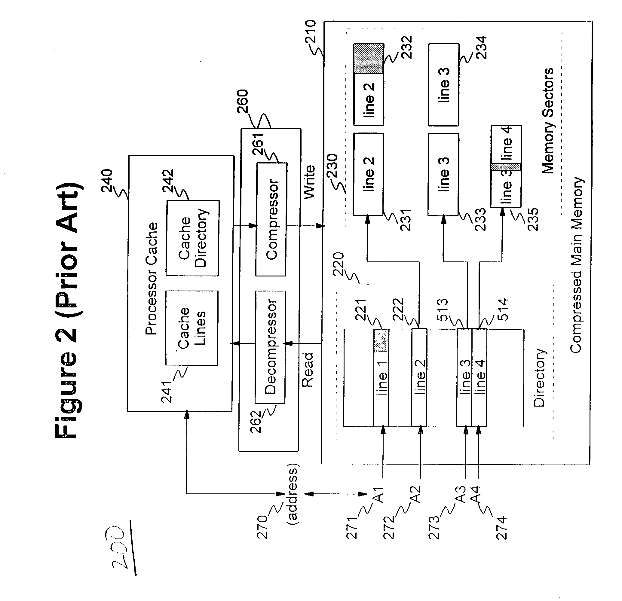
[0063] In a preferred embodiment, it is assumed that cache lines and memory lines have the same size (e.g., 1024 bytes), that memory granules are 64 bytes long, and that memory sectors are 256 bytes long and are aligned on 256-byte boundaries.

[0064] Obviously, as would be evident to one of ordinary skill in the art taking the present application as a whole, the invention is not limited to this particular choice of methods.

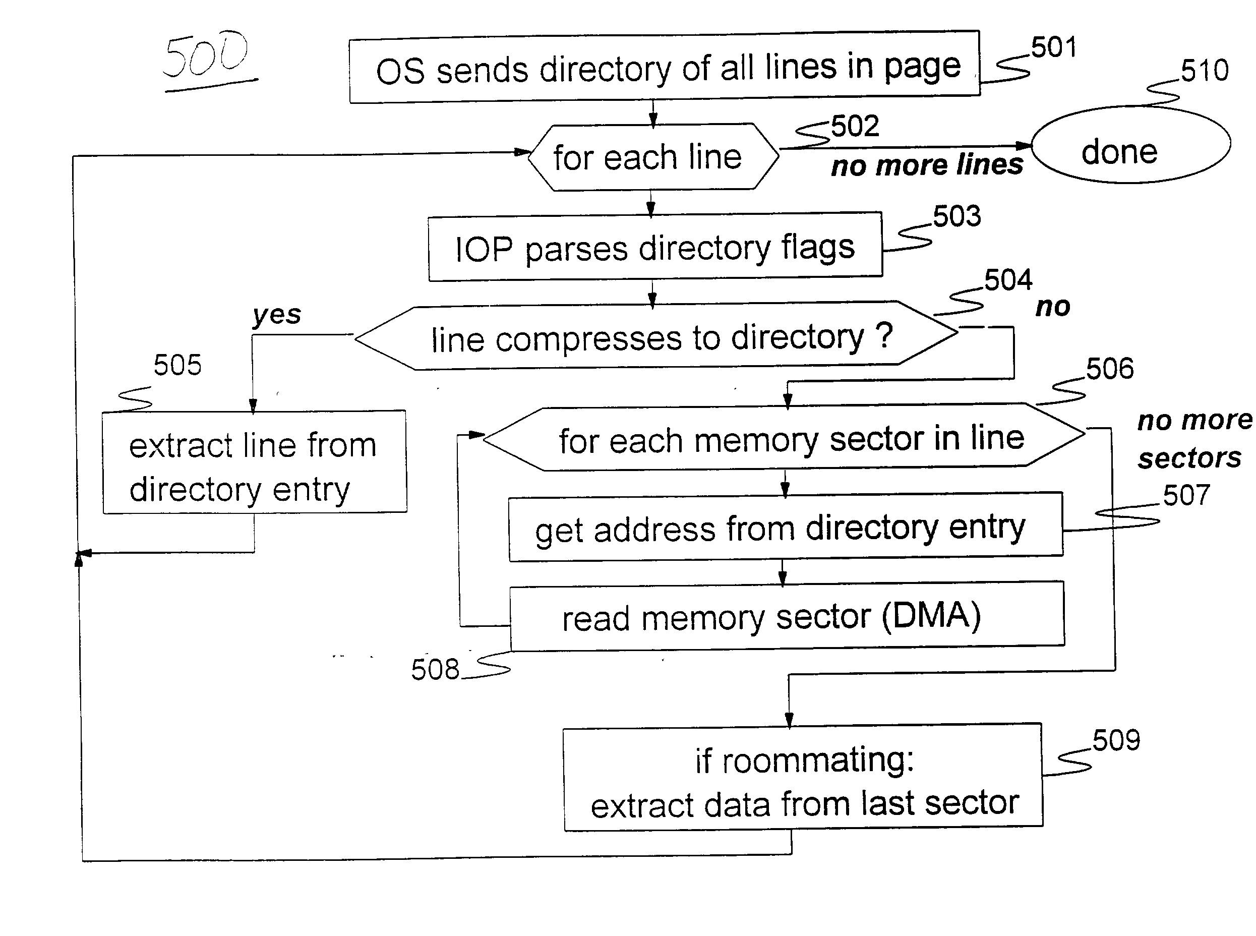
[0065] The invention has several main components, including how to transmit memory-compressed data from the processor to the IOP, and between the IOP and the disk, and how to store memory-compressed data on disk. These components will be discussed in turn below.

[0066] Transmitting Memory-Compressed Data to and from the I / O Processor / I / O Adapter (IOP / IOA)

[0067] The ...


PUM


Abstract

A method (and system) of storing information, includes storing main memory compressed information onto a memory compressed disk, where pages are stored and retrieved individually, without decompressing the main memory compressed information.

Description

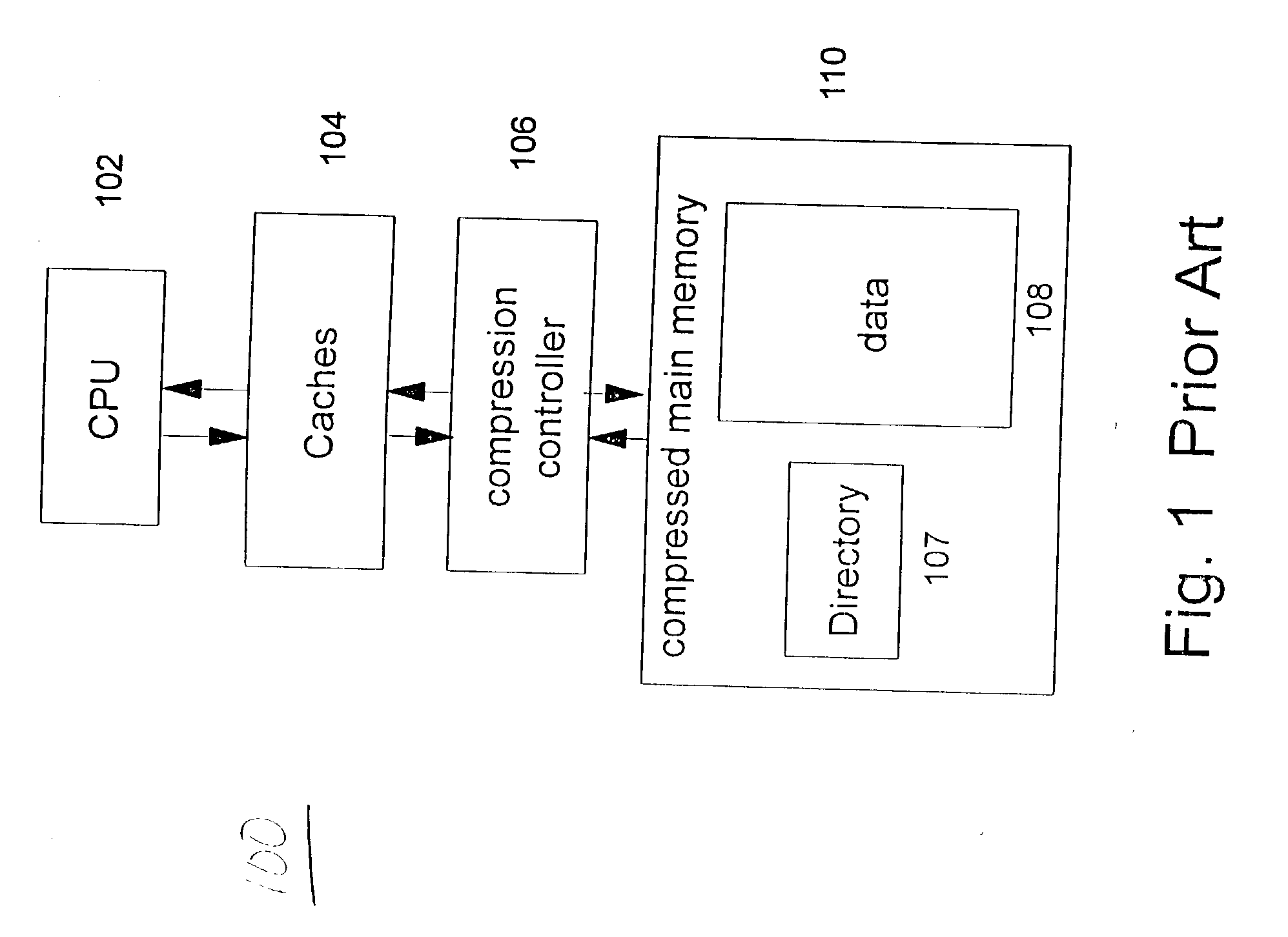
[0001] 1. Field of the Invention[0002] The present invention generally relates to compressed memory and compressed disk systems, and, more specifically, to a method for transferring memory compressed data to and from the disk adapter, and for storing memory compressed data on disk, thereby obviating the need to decompress and recompress data when transferring between memory and disk, and thus saving time and bandwidth in the system.[0003] 2. Description of the Related Art[0004] Main Memory Compression[0005] An emerging development in computer organization is the use of data compression in a computer system's main memory, where the data in the main memory is stored in a compressed format. For example, FIG. 1 shows the overall structure of an exemplary computer system 100 implementing a compressed main memory 110.[0006] In FIG. 1, a central processing unit (CPU) 102 reads data to and writes data from a cache 104. Cache "misses" and "stores" result in reads and writes to a compressed m...

Claims


Application Information

Patent Timeline
IPC IPC(8): G06F3/06G06F12/00G06F12/08G06F13/28
CPCG06F3/0608G06F3/064G06F2212/401G06F12/08G06F3/0676
Inventor BENVENISTE, CAROLINECASTELLI, VITTORIOFRANASZEK, PETER A.
Owner IBM CORP
Learn More