
Method and apparatus for controlling a display device

a display device and control method technology, applied in the direction of television systems, instruments, picture reproducers using solid-state color displays, etc., to achieve the effect of further reducing the flickering level

Inactive Publication Date: 2004-02-19
THOMSON LICENSING SA
View PDF5 Cites 12 Cited by
  • Summary
  • Abstract
  • Description
  • Claims
  • Application Information

AI Technical Summary

Benefits of technology

The present invention provides a method and apparatus for improving large area flicker reduction in PDPs. This is achieved by specific grouping of sub-fields in two consecutive groups, wherein the odd sub-fields are grouped in one group and the even sub-fields are grouped in the other group. This grouping of sub-fields ensures that in the case of the next sub-field code word being switched on due to dithering, the additional sub-field weight will be added to the group, which previously had the lower sub-field weight sum, anyhow. Thus, a relatively optimized equalization of the sub-field weights in both groups is accomplished. The large area flicker artifact on PDPs, when displaying video signals, is effectively eliminated. The method does not add extra costs and can be easily integrated into existing systems. Additionally, the invention addresses the problem of the well known 100 Hz TV mode artifact which introduces a "judder" in the video sequence. This problem can be solved by compensating one of the two 100 Hz fields in the motion direction. The invention also suggests exchanging the sub-field group position within a frame period in a predetermined frame period raster or in a randomized fashion to further reduce flickering.

Problems solved by technology

Due to the fact that both 100 Hz sub-field groups in the frame period originate from a single picture, the well known 100 Hz TV mode artifact which introduces a "judder" in the video sequence, is also a problem here.

Method used


Image

  • Method and apparatus for controlling a display device
  • Method and apparatus for controlling a display device
  • Method and apparatus for controlling a display device

Examples


Embodiment Construction

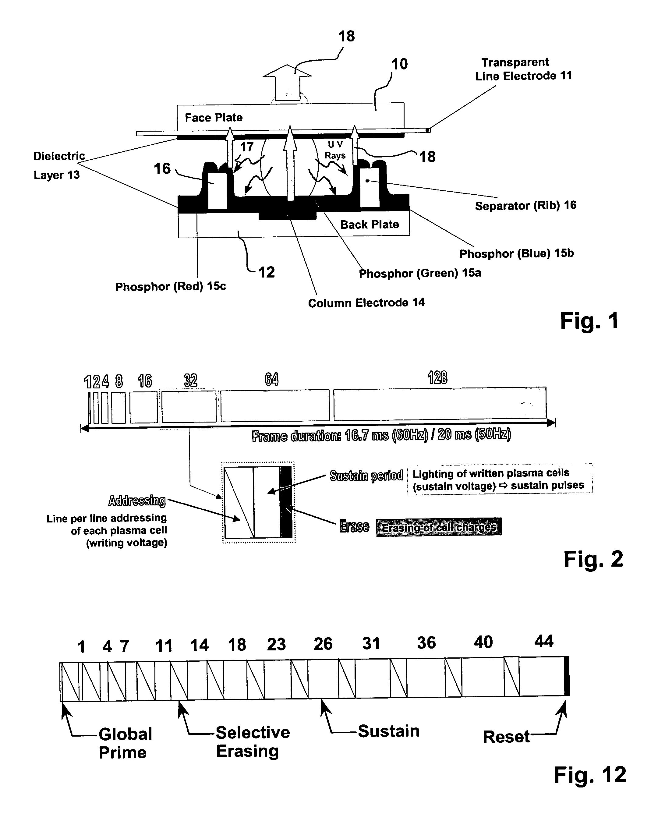
[0037] The principle structure of a plasma cell in the so-called matrix plasma display technology is shown in FIG. 1. Reference number 10 denotes a face plate made of glass. With reference number 11 a transparent line electrode is denoted. The back plate of the panel is referenced with reference number 12. There are two dielectric layers 13 for isolating face and back plate against each other. In the back plate are integrated color electrodes 14 being perpendicular to the line electrodes 11. The inner part of the cells consists of a luminous substance 15 (phosphorous) and separators 16 for separating the different colored phosphorous substances (green 15A) (blue 15B) (red 15C). The UV radiation caused by the discharge is denoted with reference number 17. The light emitted from the green phosphorous 15A is indicated with an arrow having the reference number 18. From this structure of a PDP cell it is clear, that there are three plasma cells necessary, corresponding to the three color...


PUM


Abstract

The invention deals with the large area flicker effect reduction in display devices like plasma display panels, in which the light output is controlled by small pulses over a whole frame period and the amount of small pulses determine the brightness of the light output. The invention proposes an adaptation of the known principle of sub-field grouping for large area flicker reduction for the specific sub-field coding process called incremental sub-field coding, in which only those sub-field code words are taken for display driving having the characteristic that there is never a sub-field inactivated between two activated sub-fields or never a sub-field is activated between two inactivated sub-fields. For this specific sub-field coding it is proposed to make the sub-field grouping in a simple manner, where all the odd sub-fields are grouped together in one group (G1) and all the even sub-fields are grouped together in a second group (G2). Despite the fact that some luminance differences are present in the groups it has been proved, that this sub-field grouping leads to a very efficient large area flicker reduction because of its complementary behaviour to the required dithering technique.

Description

[0001] This application claims the benefit under 35 U. International Application PCT / EP01 / 13346 filed 2001, which claims the benefit of European Appl 00403366.8, filed Nov. 30, 2000.[0002] The invention relates to a method and apparatus controlling a display device, such as matrix displays like plasma display panels (PDP), display devices with digital micro mirror arrays, (DMD) and all kinds of displays based on the principle of duty cycle modulation (pulse width modulation) of light emission.[0003] More specifically the invention is closely related to a kind of video processing for improving the picture quality and to an improved controlling of the display drivers, in particular for large area flicker effect reduction.[0004] The plasma display technology now makes it possible to achieve flat color panels of large size and with limited depth without any viewing angle constraints. The size of the displays may be much larger than the classical CPT picture tubes would have ever been al...

Claims


Application Information

Patent Timeline
Patent Type & Authority Applications(United States)
IPC IPC(8): G09G3/20H04N5/66G09G3/291G09G3/292G09G3/293G09G3/296H04N5/21H04N5/70H04N9/30
CPCG09G3/2029G09G3/204G09G3/2051G09G3/2927G09G3/2937H04N9/30G09G2320/0261G09G2320/0266G09G2320/0276H04N5/21H04N5/70G09G2320/0247G09G3/291G09G3/296
Inventor CORREA, CARLOSWEITBRUCH, SEBASTIENDOYEN, DIDIERKERVEC, JONATHAN
Owner THOMSON LICENSING SA
Learn More