Eureka AIR delivers breakthrough ideas for toughest innovation challenges, trusted by R&D personnel around the world.

In-plane switching mode LCD device and method for fabricating the same

Active Publication Date: 2004-02-19
LG DISPLAY CO LTD
View PDF16 Cites 36 Cited by
  • Summary
  • Abstract
  • Description
  • Claims
  • Application Information

AI Technical Summary

Problems solved by technology

However, LCDs have not been as successfully incorporated into these image devices because the image quality has not been fully satisfactory.
However, such driving of the liquid crystal layer provides images with a poor viewing angle.
However, the IPS mode LCD device has poor transmittance and aperture ratio because the common electrode 13 and the pixel electrode 12 are on the same plane.
Also, this charge increases the likelihood of trapping ions.
These trapped ions .crclbar. cause a leakage in the colored light, e.g., a blue light, and the colored light leakage worsens at a low temperature when motions of the ions are slow.

Method used


Image

  • In-plane switching mode LCD device and method for fabricating the same
  • In-plane switching mode LCD device and method for fabricating the same
  • In-plane switching mode LCD device and method for fabricating the same

Examples


Embodiment Construction

[0042] Reference will now be made in detail to the exemplary embodiments of the present invention, examples of which are illustrated in the accompanying drawings.

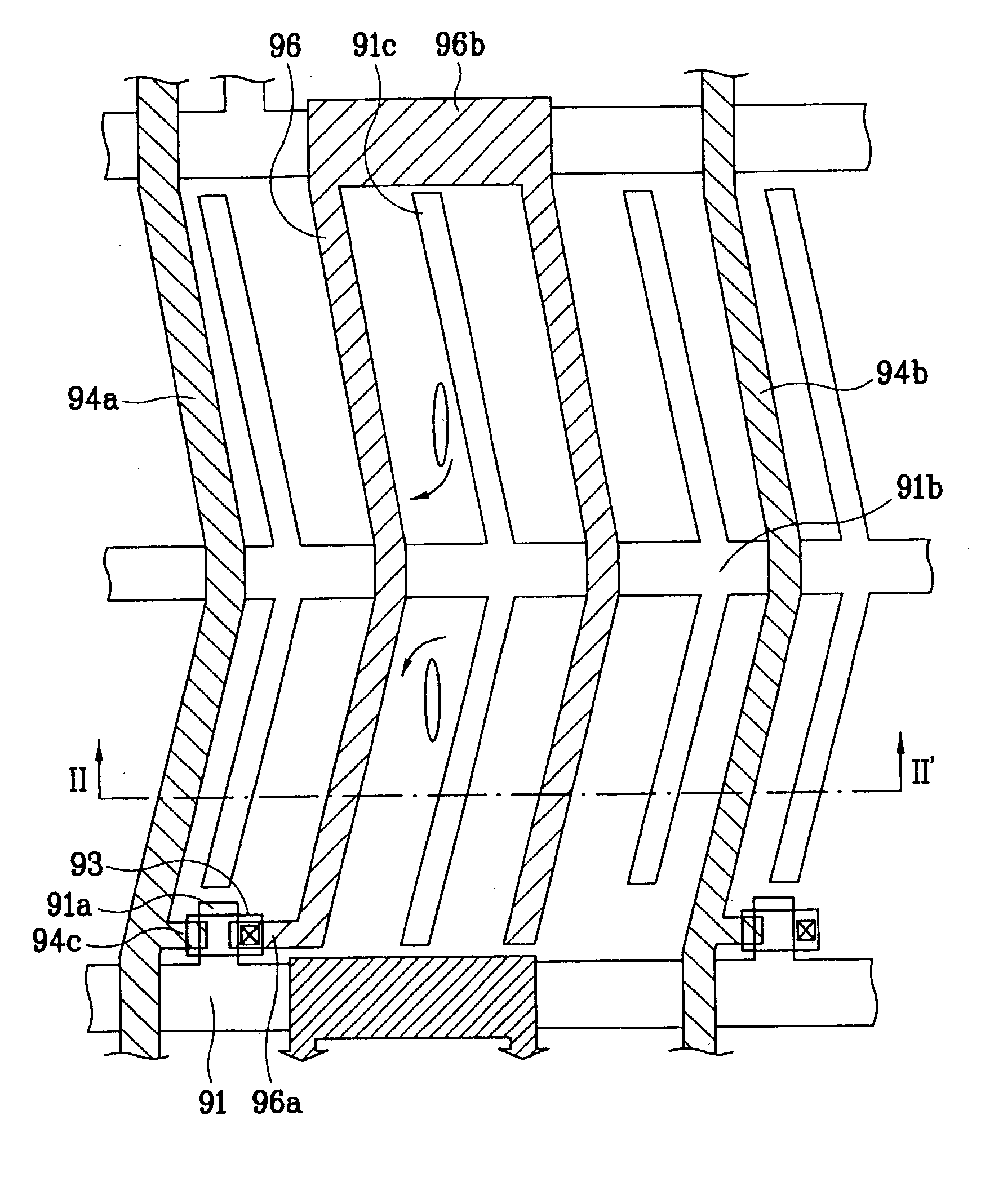
[0043] FIG. 6 is a plan view of an exemplary IPS mode LCD device according to the present invention, FIG. 7A is an enlarged plan view of `B` of the IPS mode LCD device in FIG. 6 according to the present invention, and FIG. 7B is a cross-sectional view of the IPS mode LCD device along II-II' in FIG. 7A according to the present invention. In FIG. 6, an IPS mode LCD device may include an upper substrate 80 and a transparent lower substrate 90. A sealant material 70 may be formed on either the upper substrate 80 or the lower substrate 90 for bonding the upper and lower substrates 80 and 90 to each other with a predetermined space therebetween. Also, the IPS mode LCD device may include a liquid crystal injection hole 71 for injecting liquid crystal material between the upper and lower substrates 80 and 90. In addition, the lower...


PUM


Abstract

An In-Plane Switching (IPS) mode liquid crystal display device includes a first substrate, a plurality of gate lines on the first substrate along a first direction at a predetermined interval from each other, a plurality of data lines on the first substrate along a second direction substantially perpendicular to the first direction at a second predetermined interval from each other, a plurality of pixel regions defined by the crossing of the gate and data lines, a thin film transistor on the first substrate within each of the pixel regions, at least a common line on the first substrate parallel to the gate lines, a plurality of common electrodes connected to the common line within each of the pixel regions, a dummy data line on the first substrate substantially parallel to the data lines spaced apart from an outer most common electrode adjacent to a liquid crystal injection hole, and a plurality of pixel electrodes on the first substrate within each of the pixel regions, at least one of the pixel electrodes being connected to the thin film transistor.

Description

[0001] The present invention claims the benefit of Korean Patent Application No. P2002-48656 filed in Korea on Aug. 17, 2002 and Korean Patent Application No. P2002-87872 filed in Korea on Dec. 31, 2002, which are hereby incorporated by reference.[0002] 1. Field to the Invention[0003] The present invention relates to a liquid crystal display device and a method for fabricating the same, and more particularly, to an in-plane switching (IPS) mode liquid crystal display device and a method for fabricating the same.[0004] 2. Discussion of the Related Art[0005] The vast development of information also increases the demands for the development of display devices. Recently, many efforts have been made to study and develop various types of flat display panel devices, such as liquid crystal display (LCD) devices, plasma display panel (PDP) devices, electro luminescent display (ELD) devices, and vacuum fluorescent display (VFD) devices. Some of these types of flat display panel devices have b...

Claims


Application Information

Patent Timeline
IPC IPC(8): G02F1/1341G02F1/1343G02F1/1362
CPCG02F1/1341G02F1/136286G02F1/134363
Inventor LEE, JOUN HOLEE, MIN JIE
Owner LG DISPLAY CO LTD
Why Eureka
Eureka Blog
Learn More