Method and system, with component kits for designing or deploying a communications network which considers frequency dependent effects

a technology of communication network and management system, applied in the direction of transmission monitoring, wireless commuication services, receiver monitoring, etc., can solve the problems of insufficient coverage, a "dead zone," interference in indoor wireless pbx (private branch exchange) system or wireless local area network (wlan), and the cost of in-building and microcell devices providing wireless coverage within a 2 kilometer radius is diminishing

Inactive Publication Date: 2004-02-26
EXTREME NETWORKS INC
View PDF0 Cites 52 Cited by
  • Summary
  • Abstract
  • Description
  • Claims
  • Application Information

AI Technical Summary

Benefits of technology

[0013] The communications design engineer may group several components together into a collection referred to as a "component kit". Thereafter, he or she will need only select the "component kit" for inclusion in the computerized representation of the physical environment in which the communications network will be installed. These "component kits" could be custom designed by the design engineer or, alternatively, the software package included in this system could have preselected components bundled as a "component kit". The "component kits" allow the design engineer to more simply and quickly prepare models of the communications network since he or she will be able to select essentially bundles of communications components at a time. The system; however, will be able to track all the attributes of all the components in the selected component kits, including all performance attributes, pricing information, and other physical attributes and maintenance schedules, such that calculations will automatically consider the performance criteria, pricing and compatibility for the system designed by the engineer. The component kits may be assembled in the same manner as an actual communication system, including the associated cabling and distribution system, so that connections between components are already set up when the kit is added into a system; this saves a great deal of time for the engineer.

Problems solved by technology

As wireless communications use increases, radio frequency (RF) coverage within buildings and signal penetration into buildings from outside transmitting sources has quickly become an important design issue for wireless engineers who must design and deploy cellular telephone systems, paging systems, or new wireless systems and technologies such as personal communication networks or wireless local area networks.
A common problem for wireless systems is inadequate coverage, or a "dead zone," in a specific location, such as a conference room.
It is now understood that an indoor wireless PBX (private branch exchange) system or wireless local area network (WLAN) can be rendered useless by interference from nearby, similar systems.
The costs of in-building and microcell devices which provide wireless coverage within a 2 kilometer radius are diminishing, and the workload for RF engineers and technicians to install these on-premises systems is increasing sharply.
In practice, however, a pre-existing building or campus is designed only on paper and a database of parameters defining the environment does not readily exist.
It has been difficult, if not generally impossible, to gather this disparate information and manipulate the data for the purposes of planning and implementation of indoor and outdoor RF wireless communication systems, and each new environment requires tedious manual data formatting in order to run with computer generated wireless prediction models.
While the above papers describe a research comparison of measured vs. predicted signal coverage, the works do not demonstrate a systematic, repeatable and fast methodology for creating an environmental database, nor do they report a method for analyzing system performance or visualizing and placing various wireless equipment components that are required to provide signals in the deployment of a wireless system in that environment.
While there are many methods available for designing wireless networks that provide adequate coverage, there is no easy method to ensure that the system will be cost effective.
For instance, even though the coverage may be more than adequate, given the chosen wireless infrastructure components, the total cost of the system could be prohibitive.
The component kits may be assembled in the same manner as an actual communication system, including the associated cabling and distribution system, so that connections between components are already set up when the kit is added into a system; this saves a great deal of time for the engineer.
Without such a facility, errors may not be discovered until installation or use of the system, at which point they are far more costly to repair.

Method used


Image

  • Method and system, with component kits for designing or deploying a communications network which considers frequency dependent effects
  • Method and system, with component kits for designing or deploying a communications network which considers frequency dependent effects
  • Method and system, with component kits for designing or deploying a communications network which considers frequency dependent effects

Examples


Embodiment Construction

Design of Wireless Communication Systems

[0038] Using the present method, it is now possible to assess the RF environment in a systematic, organized fashion by quickly viewing signal strength, or interference levels, or other wireless system performance measures. The current embodiment is designed specifically for use with the SitePlanner.TM. suite of products available from Wireless Valley Communications, Inc. of Blacksburg, Va. However, it will be apparent to one skilled in the art that the method could be practiced with other products either now known or to be developed in the future. (SitePlanner is a trademark of Wireless Valley Communications, Inc.)

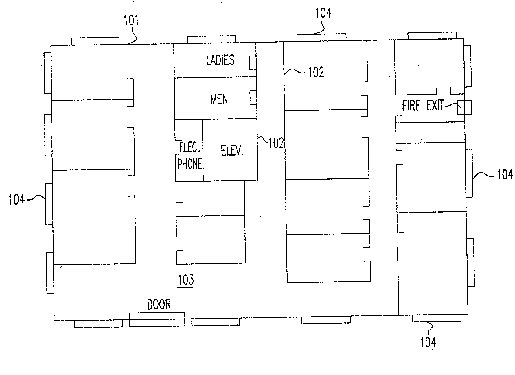
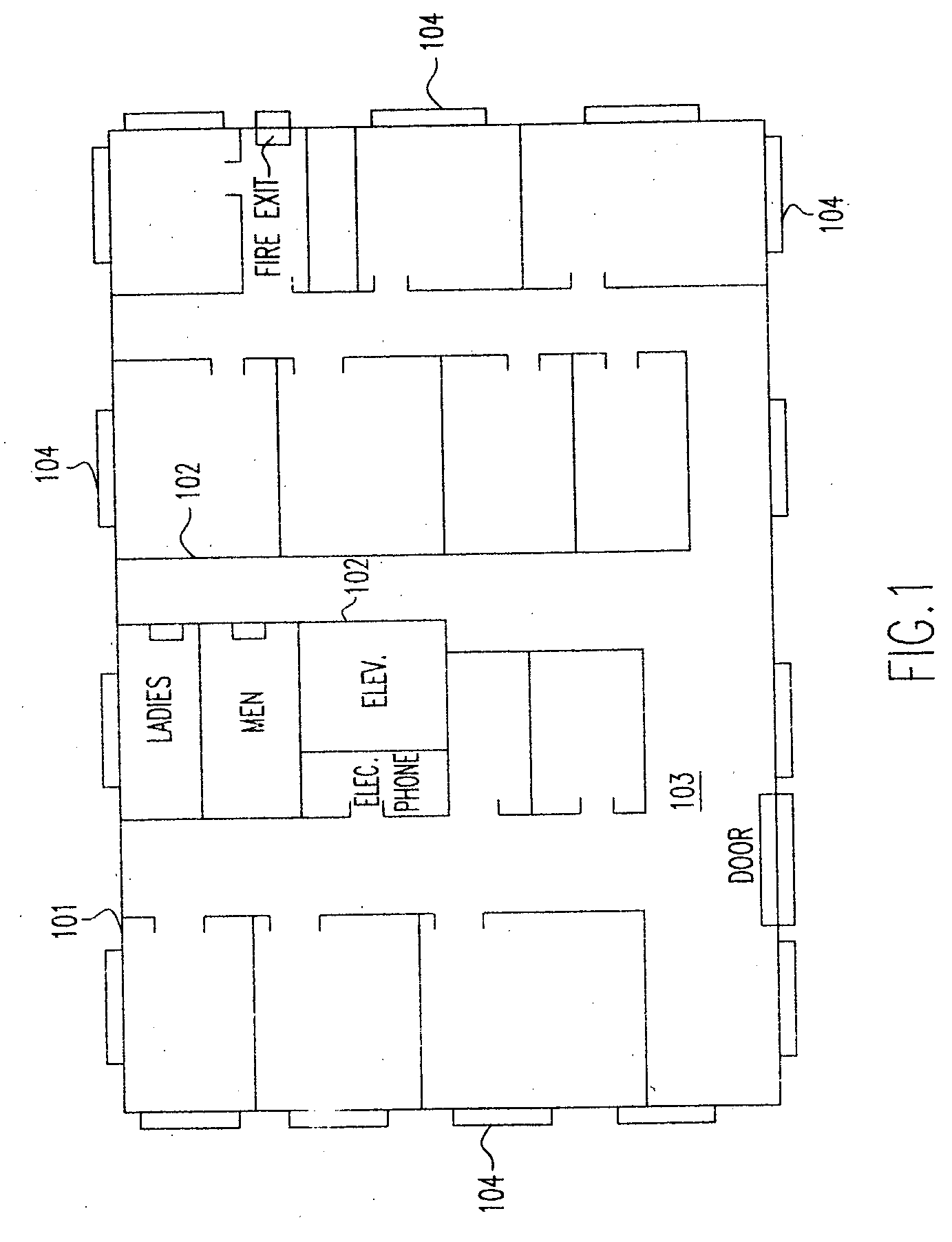
[0039] Referring now to FIG. 1, there is shown a two-dimensional (2-D) simplified example of a layout of a building floor plan. The method uses 3-D computer aided design (CAD) renditions of a building, or a collection of buildings and / or surrounding terrain and foliage. However, for simplicity of illustration a 2-D figure is used. Th...


PUM


Abstract

A computerized model provides a display of a physical environment in which a communications network is or will be installed. The communications network is comprised of several components, each of which are selected by the design engineer and which are represented in the display. Errors in the selection of certain selected components for the communications network are identified by their attributes or frequency characteristics as well as by their interconnection compatibility for a particular design. The effects of changes in frequency on component performance are modeled and the results are displayed to the design engineer. A bill of materials is automatically checked for faults and generated for the design system and provided to the design engineer. For ease of design, the design engineer can cluster several different preferred components into component kits, and then select these component kits for use in the design or deployment process.

Description

[0001] This application is related to the co-pending U.S. patent application Ser. No. 09 / 352,678 filed Jul. 14, 1999, now U.S. Pat. No. 6,499,006; Ser. No. 09 / 318,840 filed May 26, 1999, now U.S. Pat. No. 6,317,599; Ser. No. 09 / 318,841 filed May 26, 1999; and Ser. No. 09 / 318,842 filed May 26, 1999, now U.S. Pat. No. 6,493,679; and is also related to the concurrently filed applications having U.S. Ser. No. 09 / 632,853, entitled "Method and System for Designing or Deploying a Communications Network which Considers Component Attributes"; and Ser. No. 09 / 633,133, entitled "Method and System for Designing or Deploying a Communications Network which Allows the Simultaneous Selection of Multiple Components", all of which are assigned to a common assignee, and the subject matter of these applications is incorporated herein by reference.DESCRIPTION[0002] 1. Field of the Invention[0003] The present invention generally relates to engineering and management systems for the design of communicatio...

Claims


Application Information

Patent Timeline
Patent Type & Authority Applications(United States)
IPC IPC(8): H04B17/00H04W16/18H04W16/20
CPCH04W16/20H04B17/23H04B17/3913H04B17/318H04B17/336H04B17/309
Inventor RAPPAPORT, THEODORE S.SKIDMORE, ROGER R.REIFSNEIDER, ERIC
Owner EXTREME NETWORKS INC
Why Eureka
Try Eureka