Latent fault detection in redundant power supply systems

Active Publication Date: 2004-02-26
ORACLE INT CORP
View PDF10 Cites 33 Cited by
  • Summary
  • Abstract
  • Description
  • Claims
  • Application Information

AI Technical Summary

Benefits of technology

0005] Embodiments of the present invention seek to provide an improved method of late

Problems solved by technology

If correct operation is not confir

Method used


Image

  • Latent fault detection in redundant power supply systems
  • Latent fault detection in redundant power supply systems
  • Latent fault detection in redundant power supply systems

Examples


Example

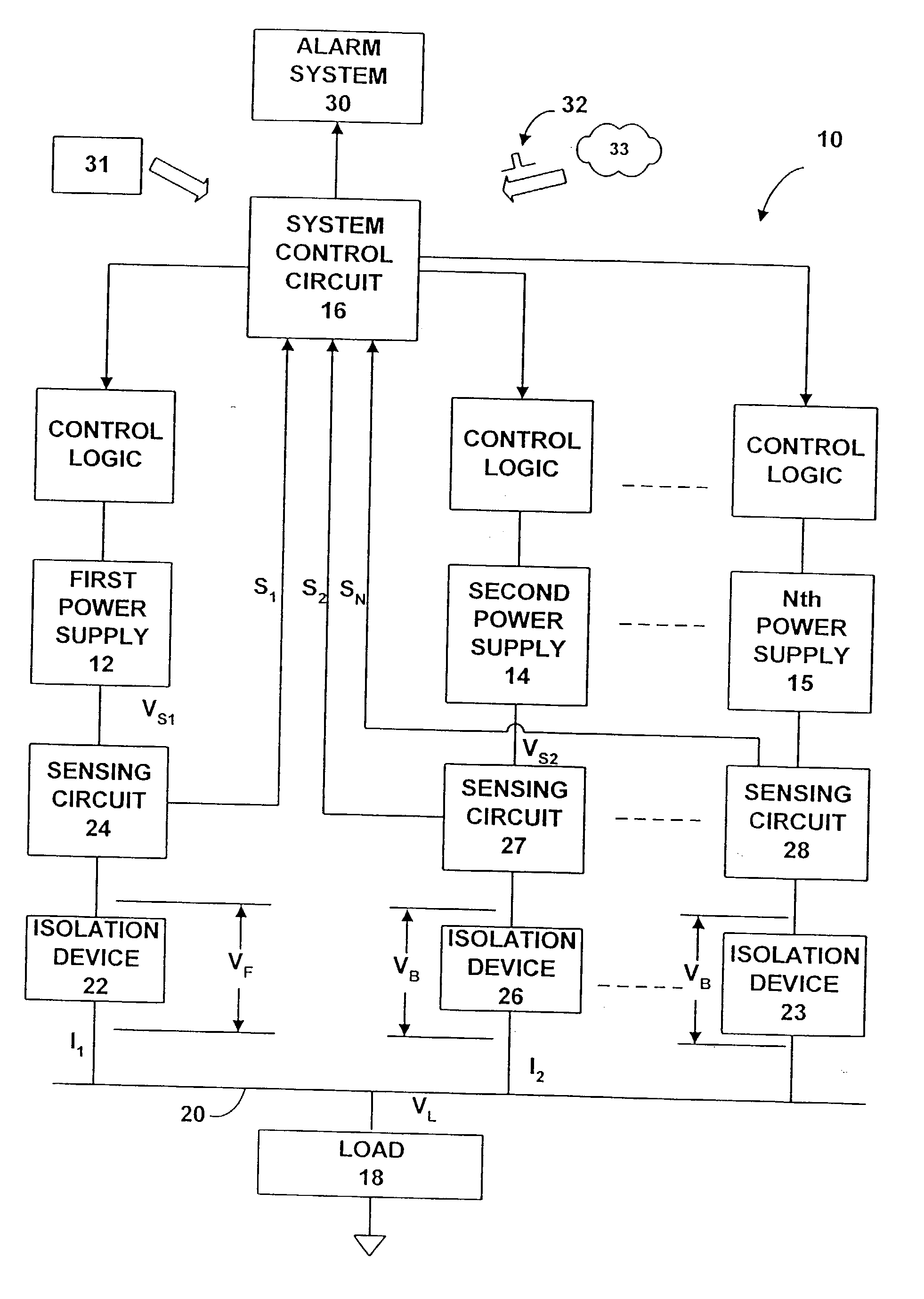
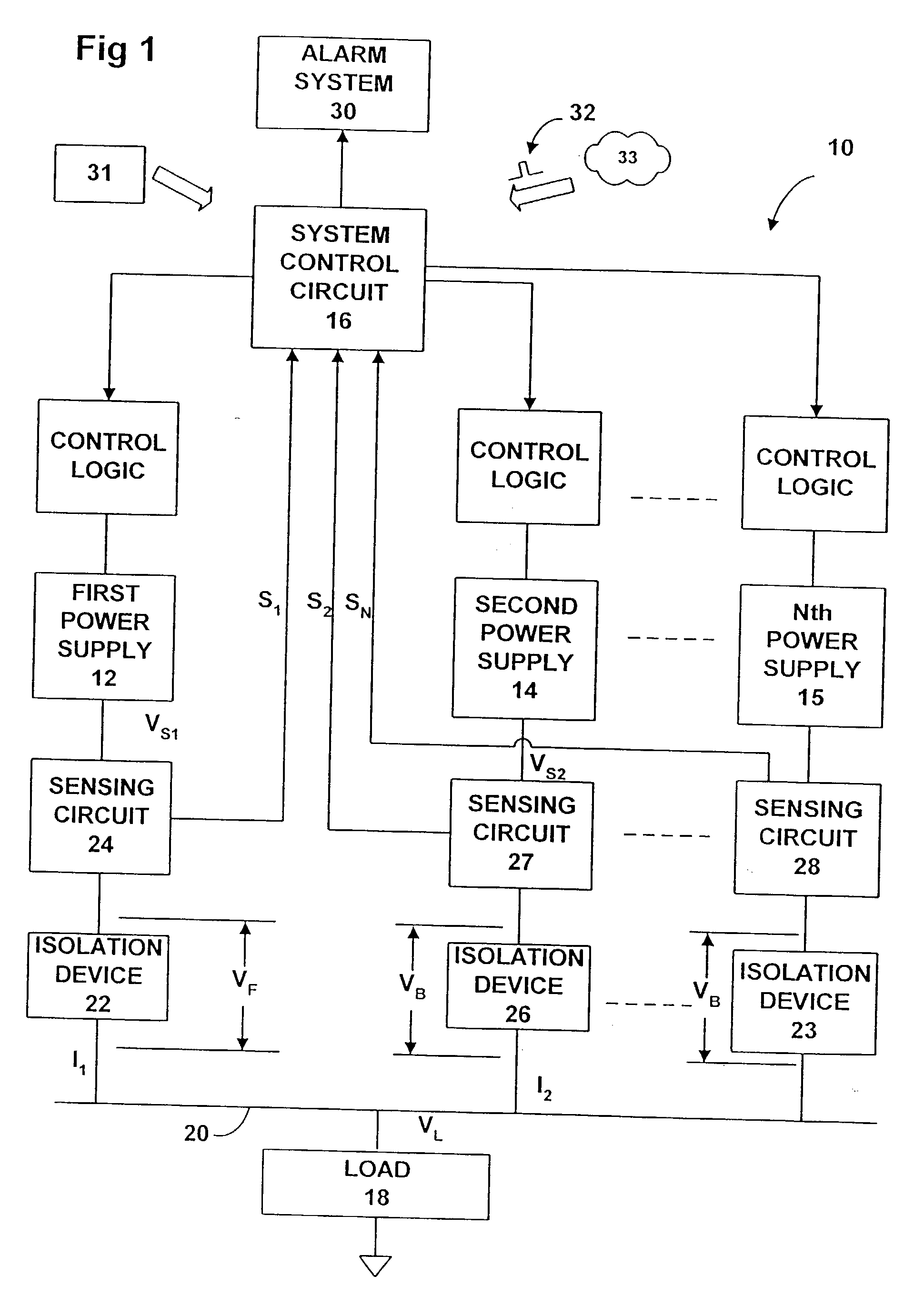
[0013] FIG. 1 illustrates a power supply system 10 comprising a series of N power supplies of which a first power supply 12, a second power supply 14, and an Nth power supply 15 are shown, each power supply of the system being connected to a system control circuit 16.

[0014] The power supplies 12, 14, 15 are arranged in parallel to supply a load 18 with a load voltage V.sub.L via a power bus 20.

[0015] Each power supply 12, 14, 15 is provided with a respective isolation device so that, as shown in FIG. 1, a first isolation device 22 is connected in series with the first power supply 12 and is arranged to conduct current in only one direction, from the power supply to the power bus 20.

[0016] A first current sensing circuit 24 is connected in series with the first isolation device 22 to detect the magnitude and direction of current I.sub.1 through the first isolation device.

[0017] Respective isolation devices and current sensing circuits are similarly connected for each of the remaining...


PUM


Abstract

Latent faults are detected by a testing system in a redundant DC power supply system having at least two power supplies connected to a common load via respective isolation devices. The testing system selects as a subject for a test procedure one isolation device and its corresponding power supply. The power supplies are controlled during the test procedure to marginally vary the output voltage of at least one power supply such that a differential voltage is applied between the output of the selected power supply and the outputs of the remaining power supplies for selectively changing the conductive state of at least one isolation device to a non conductive state by reducing its forward voltage to less than its respective forward bias voltage value.

Description

[0001] This invention relates to power supply systems in which a plurality of DC power supplies are arranged to supply a common load, at least one of the power supplies being redundant during normal operation such that the system is capable of continuing to supply the load in the event of failure of one of the power supplies.[0002] It is customary for each power supply to be provided with a respective isolation device such as a diode to prevent any unwanted backflow of current under any circumstances where the power supply to which it is connected is inoperative, whether intentionally or due to malfunction.[0003] A latent fault may exist if an isolation device fails, for example by developing a short circuit fault, there being apparently no overall change in the operational status of the system while its power supply continues to be operative. Since, however, the integrity of the isolation device is relied upon in the event of power supply failure, the existence of a latent fault ca...

Claims


Application Information

Patent Timeline
IPC IPC(8): G01R31/30G01R31/40G06F1/28G06F11/20H02J1/10
CPCG01R31/30G01R31/40H02J1/108G06F11/2015G06F1/28
Inventor GARNETT, PAUL J.
Owner ORACLE INT CORP
Why Eureka
Try Eureka