
All weather wind turbines

a wind turbine and all weather technology, applied in the field of wind turbines, to achieve the effect of reducing the spin

Inactive Publication Date: 2004-03-04
KHAN GHAZI
View PDF2 Cites 13 Cited by
  • Summary
  • Abstract
  • Description
  • Claims
  • Application Information

AI Technical Summary

Benefits of technology

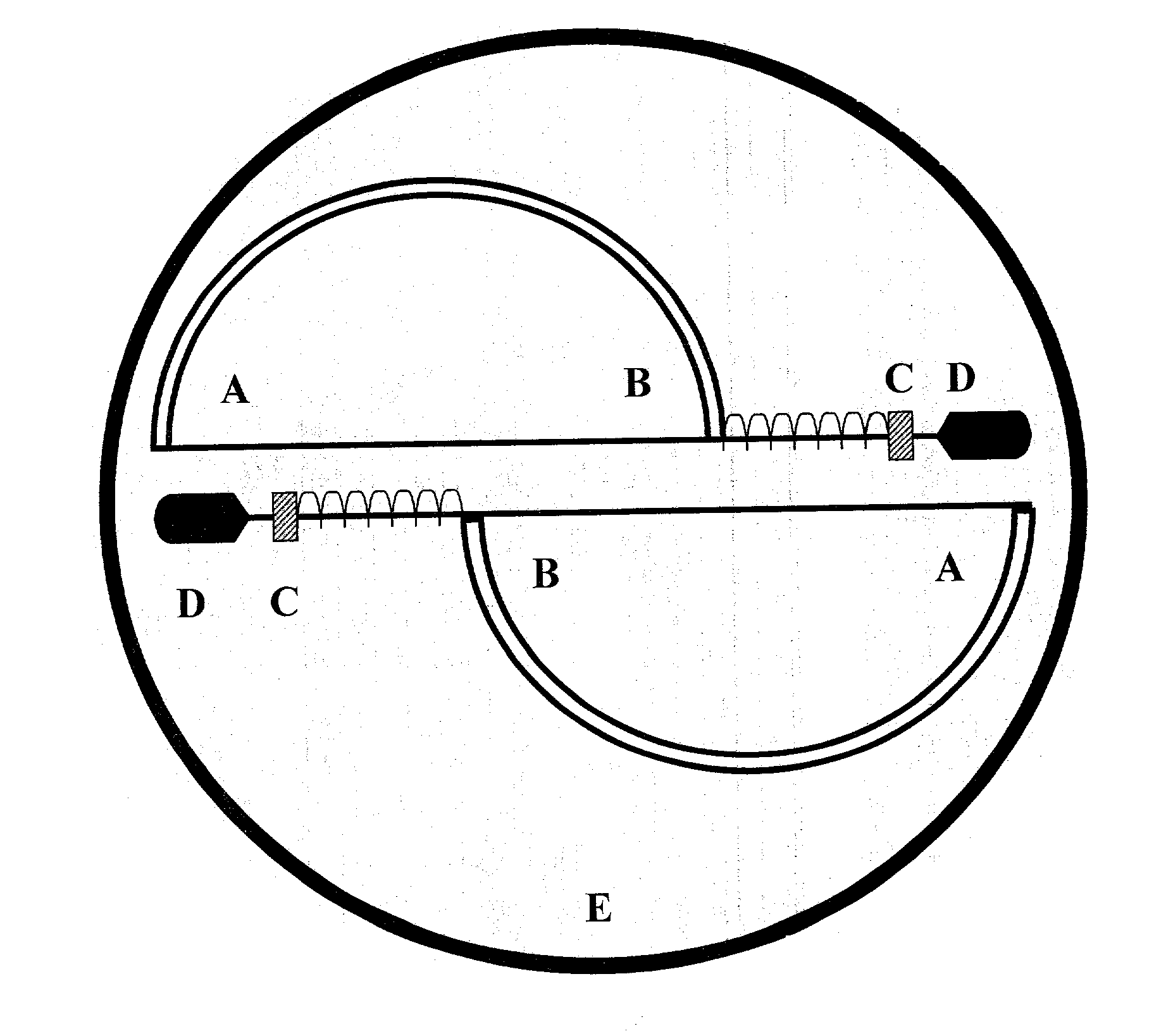
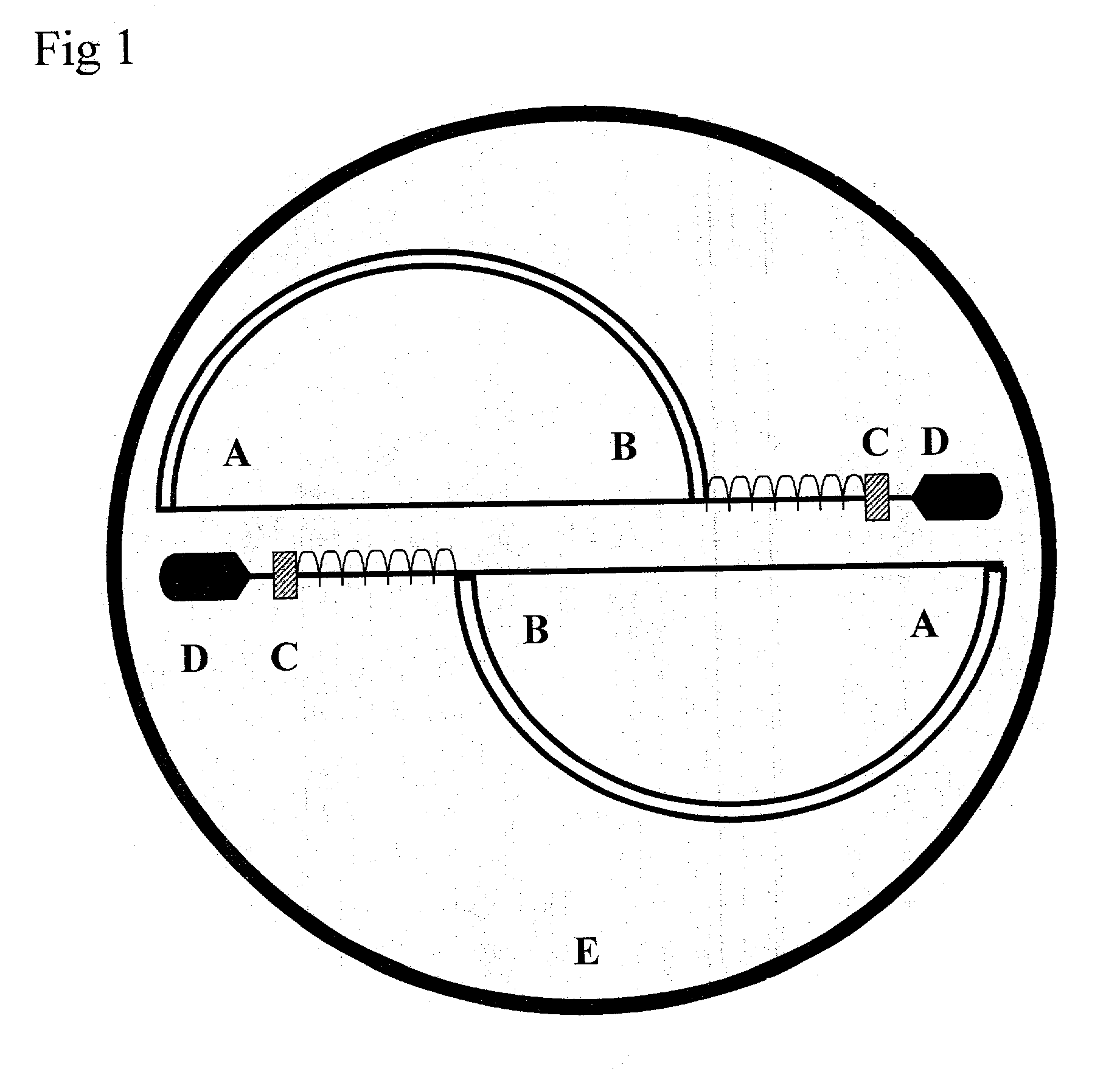
0007] The wind accelerates the RPMs of rotors whereas the centrifugal force acts in sync with the rotation of the rotor blades. More spin creates more centrifugal force which in turn draws the sliding rotor blades towards the center, closing the air intake gates and reducing the spin automatically as and keeps the spin steadier though rough gusty windy conditions without damaging the assembly. The technology of this utility works with the changing winds to provide unsupervised operation continuously.

Problems solved by technology

The technology of this utility works with the changing winds to provide unsupervised operation continuously.

Method used


Image

  • All weather wind turbines
  • All weather wind turbines
  • All weather wind turbines

Examples


Embodiment Construction

[0016] FIG. 1 shows "A & B" two sides of the rotor blades. A spring or any elastic medium is placed at the outer edge of the rotor blade "B" and the stopper "C" whereas a rod or cable is passed through this spring "BC" and connected to a weight "D". The weights are heavier than the rotor blade on the other side from the center or if equal in weight, are placed at a more distance from the center to create more centrifugal force to draw the rotor towards the center of the platform "E". The weights are elastic medium are calibrated with the wind speed and the size of the rotor blades so that the wind inlet blade cavity overlap the counter blade and reduce the intake of air at higher RPMs.

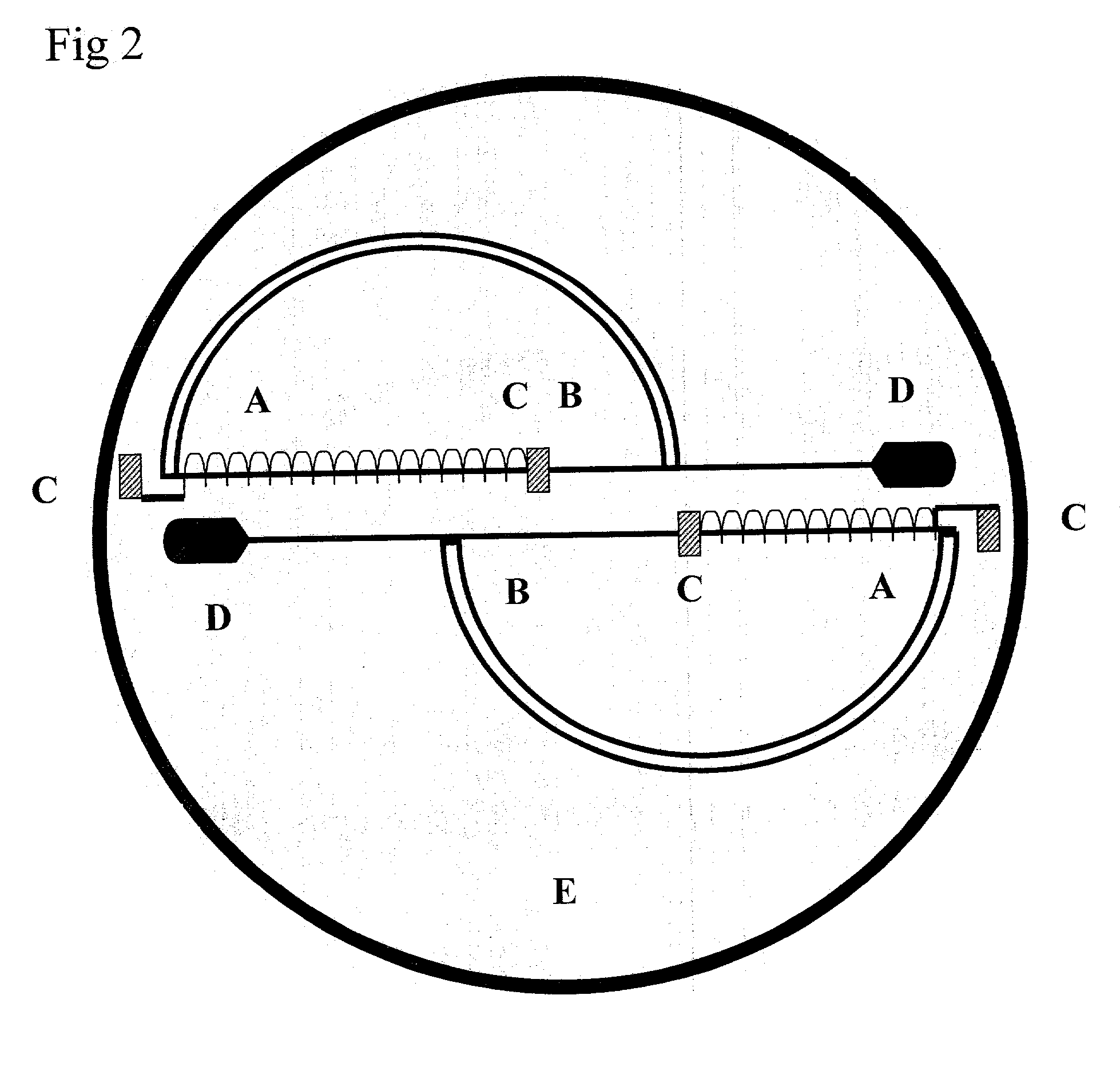
[0017] FIG. 2 has the only difference that instead of using the pressure at point "B" and causing the expanded spring or elastic medium to shrink by the centrifugal force, in FIG. 2 the spring or elastic medium is pulled to expand from point "A" by the weight "D" due to the centrifugal force effect cau...


PUM


Abstract

The technology of all weather wind turbine is disclosed by applying it to a savonius design wind turbine although it can be applied to all kinds of windmills based on rotational mechanism in general and specifically in the field of wind turbines. In this current embodiment the art is used to a savonius design rotor. A Savonius rotor assembly includes two blades. Each of the blades has an outer edge and an inner edge with the outer edges of the blades lying on a circle which define the diameter of the rotor. Each of the blades has a linear portion adjacent to the inner edge and a first curved portion which is substantially an arc of a circle tangent to the linear portion and tangent to the circle defining the rotor diameter. A second curved portion is substantially coincident to the circle defining the rotor diameter. In some applications multiple blades or multiple units are mounted in layers for more torque. The major modifications however from savonius type turbine are as follows: First feature of this preferred embodiment is the free sliding movement of rotor blades / air foils cushioned by elastics / springs and balanced by counter weights. Secondly a smart self regulating system, enabling the assembly not only to survive the windy storms but also provide steadier RPMs by shutting the wind inlet gates, corresponding to the increase in RPMs caused by the gusty winds. The central shaft between the air foils can be eliminated if so desired to give free passage to the air to improve efficiency however the basic emphasis is on the principle of automatic governor mechanism rather than the rotor blade shape or angle of curve.

Description

I. BACKGROUND OF THE INVENTION[0001] 1. Field of the Invention[0002] This invention pertains to a wind turbine. More particularly, this invention pertains to a wind turbine with a Savonius-design blade assembly with a self regulating mechanism to allow continuous and steady output in unpredictable windy conditions.[0003] 2. Description of the Prior Art[0004] Savonius-type rotors is well known. Examples of such are illustrated in U.S. Pat. No. 4,784,568 and U.S. Pat. No. 4,359,311. The rotor blades are generally semi-cylindrical in shape in contrast to conventional turbines which have inner edges of the blades fixed to adjoining blades or to a central core, drum or shaft. In the design and development of Savonius rotors, the geometry of the rotor blades impacts on the power coefficient of the rotor. Accordingly, the development of blade geometry is an ongoing development for the purpose of improving the performance of Savonius rotors.[0005] It is an object of the present invention to...

Claims


Application Information

Patent Timeline
Patent Type & Authority Applications(United States)
IPC IPC(8): F03D3/00F03D7/06
CPCF03D3/005Y02E10/74F05B2240/213F03D7/06
Inventor KHAN, GHAZI
Owner KHAN GHAZI
Learn More