Deformable pull plug

a pull plug and deformation technology, applied in the direction of liquid handling, application, and closure using stoppers, can solve the problems of affecting the ability of the operator, affecting the appearance of the coating part, and further affecting the ability to form a complete seal, so as to reduce the defect of the coating and improve the appearance of the coated par

Inactive Publication Date: 2004-03-25
ENGINEERED PRODS & SERVICES
View PDF12 Cites 30 Cited by
  • Summary
  • Abstract
  • Description
  • Claims
  • Application Information

AI Technical Summary

Benefits of technology

[0024] Yet another object is to provide an improved pull plug which is simple and easy to use.
[0077] An important advantage of the inventive plug 10 versus conventional washer plugs is the capability of the pull plug 10 to be removed through part opening 85 in the direction of arrow 105. Removal of the plug 10 in the same direction as insertion of the plug 10 results in a clean break between the plug 10 and the applied coating improving the appearance of the coated part and reducing defects in the coating.

Problems solved by technology

Depending on the specific application for the part, contact between the coating and the internal surface portions of the part can be undesirable and can severely damage the part.
These threads about the part opening pose a particular problem with respect to limiting the migration of coating material into the interior portions of the part.
More specifically, the protruding threads interfere with the operator's ability to form a complete seal over the part opening blocking the flow of coating material into the part.
Yet another complication involving threaded openings relates to the fact that the first thread of the threaded opening is typically chamfered and is not flat or smooth.
The chamfered edge further interferes with the ability to form a complete seal over the opening.
Failure to fully mask the first thread of the chamfered opening may permit coating materials to contact and build up on the threads damaging the threads and preventing engagement with the fastener or other part following completing of the coating or other work process.
Unwanted application of coating to the threads can result in costly re-working expenses or loss of the part.
The different surface geometries about the part opening present an obstacle to forming a complete mask over such surfaces.
As will be readily understood by those of skill in the art, serious contamination of a threaded part opening tapped directly into the part could potentially result in loss of the entire part.
During manufacturing of the product, flux and metal contaminants from welding operations near the weld nut can undesirably become attached to the weld nut in or near the weld nut threaded opening.
Any such contamination may require costly cleaning or re-working of the threaded opening in the weld nut or may even require removal of the weld nut.
Yet a further factor complicating coating and manufacturing processes is the fact that there is an almost infinite variation in the types of part openings that may be encountered.
Each different type of part opening potentially represents a unique set of problems with respect to masking of the opening.
Because thousands of masking devices may be required for a large production run, the operator is required to maintain a large inventory of plugs.
While conventional plugs are very effective in masking typical part openings, such plugs are less than fully effective in masking specialized part openings such as threaded openings, countersunk openings and other openings having more unique configurations.
A less than complete seal may be formed because the more rigid material typically used to make these plugs does not fully seal the helical passageway formed by the threads.
By way of further example, conventional plugs, including pull plugs, lack structure to shield the chamfered edge of the threaded opening from contact with coating material or contaminants.
The higher durometer material used in the washer flanges limits the capability of the plug to conform to the irregular surfaces about the part opening.
A further disadvantage of washer plugs involves the fact that such plugs must be removed from the part opening in a direction opposite to the direction in which the plug was inserted.
Removal of the washer plug in the direction opposite to the direction of insertion can result in an irregular tearing of the applied coating material around the location of the plug damaging the coated part.
As a further example, conventional plugs, including pull plugs, are also ineffective in masking countersunk portions about the part opening, such as the tapered annular portions located about the annulus of a part opening.
Such conventional plugs are not effective in masking the countersunk portion because the plug body is sized to approximate the opening and is not sized sufficiently to mask the larger countersunk region surrounding the opening.

Method used


Image

  • Deformable pull plug
  • Deformable pull plug
  • Deformable pull plug

Examples


example 1

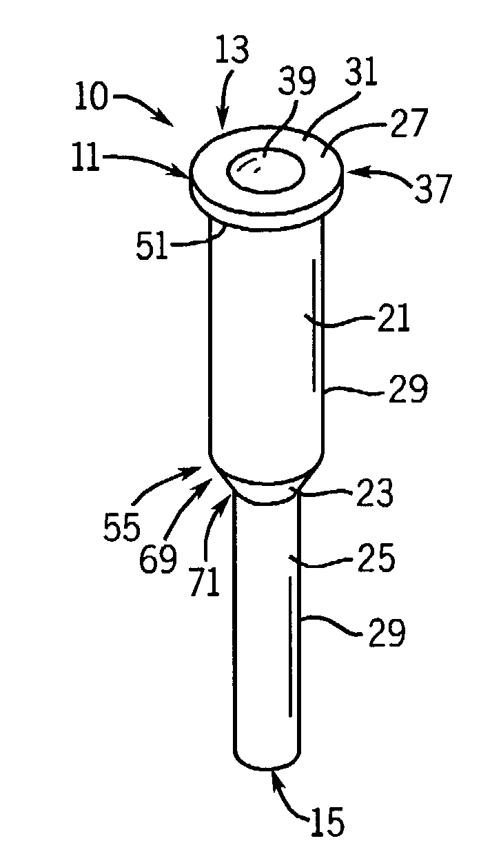
[0078] An important advantage of the inventive plug 10 is that a single pull plug 10 can be used to mask a wide range of part openings each having different opening sizes. As a result, an operator need not maintain as great an inventory of plugs for the operator's coating or other operation. Since thousands of plugs in different sizes may be needed to operate a large scale coating operation, this can result in significant savings in inventory and material for the operator. This advantageous result is possible because of the combination of (1) the void volume 39; and (2) the novel plug body 11 made of the highly deformable material having a low durometer value of 35-45 on the Shore A scale. The combination of these elements permits one plug 10 to deform to fit many smaller part openings (such as opening 85).

[0079] A comparison of prior art pull plugs and pull plugs of the invention was conducted to determine the range of part openings which could be fully masked with a single size pl...

example 2

[0082] A further important advantage of the inventive plug 10 is that a single pull plug 10 can be repeatedly reused during the course of many coating cycles. The ability to reuse the plug permits an operator to maintain a smaller inventory of plugs for the operator's coating or other operation. Again, this can result in significant savings in inventory and material for the operator.

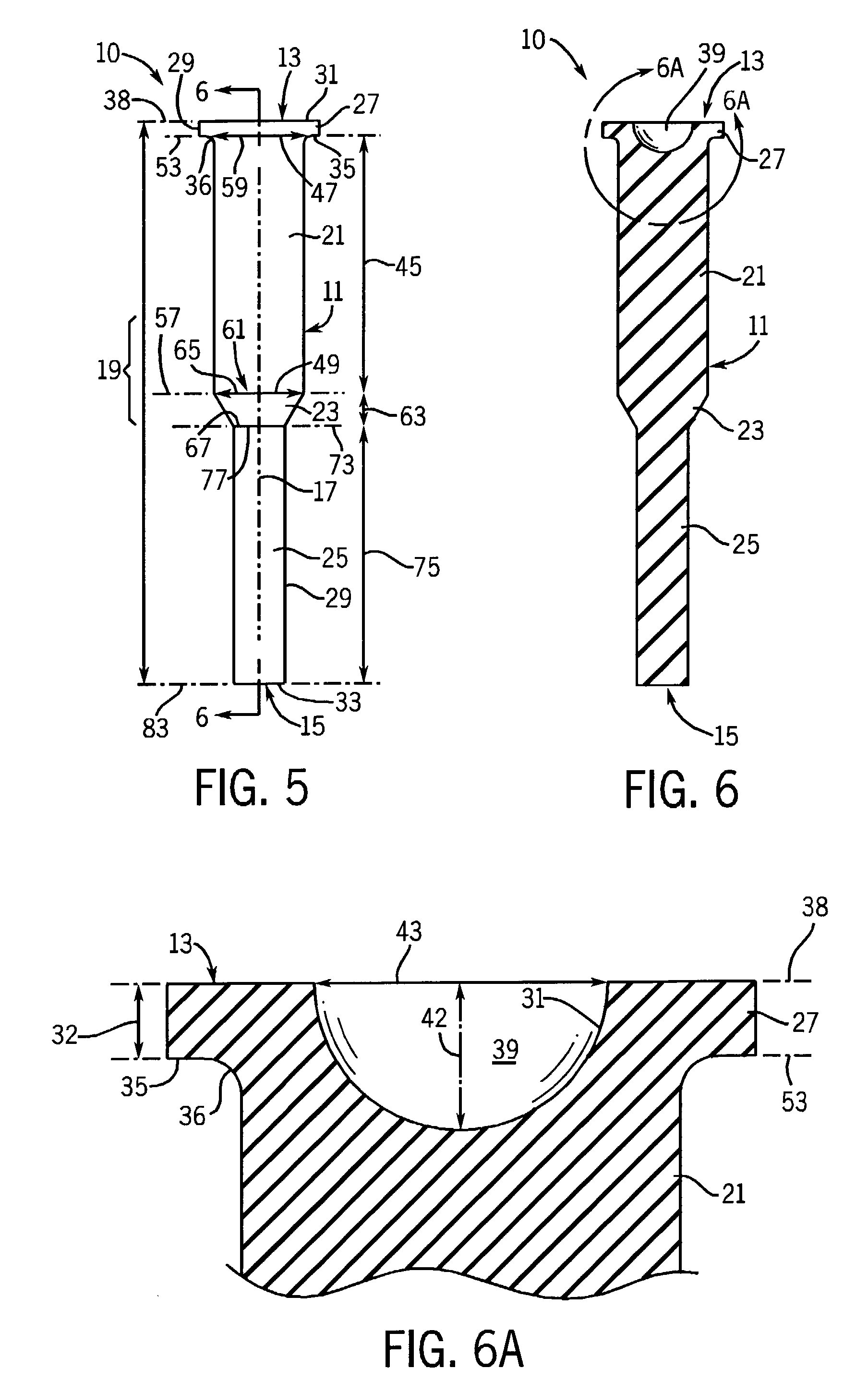
[0083] Control and inventive pull plugs having the geometry of the plugs shown in FIGS. 1-12 were manufactured. The plugs had identical flanges 27 and plug 21, transition 23 and tail 25 segments. Both plugs were made of virgin silicone. The plugs differed only in that the control plug lacked a void volume 39 and had a durometer of 55+ / -5 on the Shore A scale while the inventive plug included a hemispherical void volume 39 as shown in FIGS. 1-12 and had a durometer of 40+ / -5 on the Shore A scale.

[0084] The pull plugs were inserted into a 1 / 4-20 threaded opening in a template and were pulled completely thr...


PUM


Abstract

A reusable pull plug for masking part openings in parts to be coated or otherwise worked upon. The pull plug has particular utility in masking irregular surface portions about the part opening including, without limitation threaded, chamfered, stepped and spot faced surfaces. The pull plug is comprised of a deformable, segmented body including plug, transition and tail body segments. A flange and void volume, or "dimple," are formed in one plug body end adjacent the plug segment. The pull plug is pulled into the part opening by the tail segment and the plug segment forms a frictional fit with the deformable body tightly sealing the part opening. The flange covers the first thread in threaded part openings and further covers chamfered, stepped and spot faced surfaces protecting those surfaces from contact by the coating or other materials. The void volume facilitates deformation of the flange and plug segment permitting the flange to conform to the surface about the part opening and permitting the pull plug to be withdrawn through the part opening in the same direction as inserted thereby avoiding damage to the applied coating material. The novel design reduces stresses on the pull plug and enables the plug to be reused through repeated coating or operation cycles.

Description

[0001] This invention is related generally to masking apparatus and, more specifically, to masking apparatus for covering openings in parts during coating and other operations.[0002] Many types of manufactured parts, such as parts used in fabrication, aerospace and final assemblies must be coated with various materials and substances to adapt those parts for their intended end use. Such coatings are typically selected to impart desired characteristics to the coated part. For example, the coating may impart corrosion resistance to the part or may be selected to impart a selected surface finish or cosmetic appearance to the part.[0003] As is known, many different types of materials can be applied to the parts during coating operations. These materials include, for example, nylons, polycarbonates, metals and other known materials.[0004] There are many coating technologies available and the specific coating procedure can be selected based on the specific application. Modern coating oper...

Claims


Application Information

Patent Timeline
Patent Type & Authority Applications(United States)
IPC IPC(8): B05B15/04
CPCB05B15/0462B05B12/26
Inventor SARAJIAN, TIGRAN K.
Owner ENGINEERED PRODS & SERVICES
Why Eureka
Try Eureka