Oscillator, PLL circuit, communication equipment, and oscillating method

Active Publication Date: 2004-04-08
PANASONIC CORP
View PDF4 Cites 31 Cited by
  • Summary
  • Abstract
  • Description
  • Claims
  • Application Information

AI Technical Summary

Problems solved by technology

However, such a voltage-controlled oscillator creates the following problems: (1) If noise is superimposed on a voltage control line (i.e. a line leading to the voltage control terminal), the voltage across the varactor 105 may change to change the oscillation frequency.
(3) Such

Method used


Image

  • Oscillator, PLL circuit, communication equipment, and oscillating method
  • Oscillator, PLL circuit, communication equipment, and oscillating method
  • Oscillator, PLL circuit, communication equipment, and oscillating method

Examples


embodiment 1

[0089] (Embodiment 1)

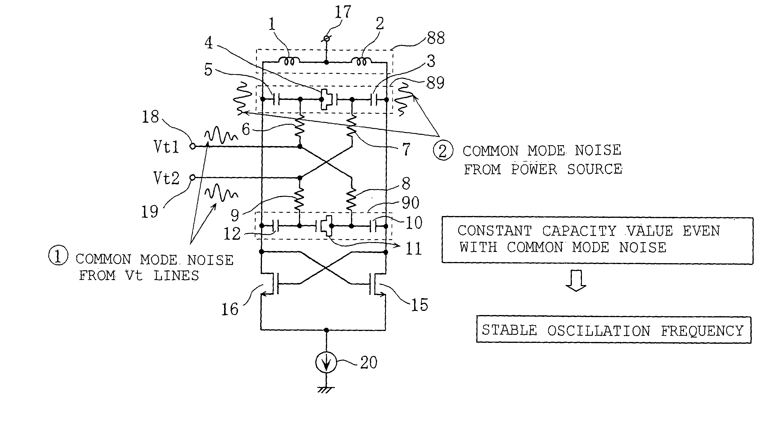
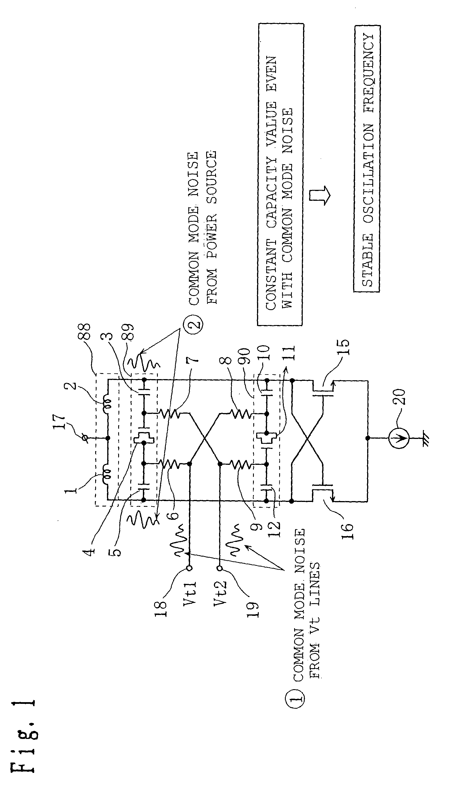
[0090] FIG. 1 shows a circuit of an oscillator according to Embodiment 1 of the present invention. The circuit shown in FIG. 1 has a first series connected circuit 88 as an example of a first series connected circuit according to the present invention which circuit comprises a coil 1 as an example of an inductive impedance element according to the present invention, a coil 2 as another example of an inductive impedance element according to the present invention which coil is connected in series with the coil 1, and a power terminal 17 as an example of a power terminal according to the present invention which terminal is connected between the coils 1 and 2 for a power supply; a second series connected circuit 89 as an example of a second series connected circuit according to the present invention which circuit comprises a capacitor 5 as an example of a first capacitive impedance element according to the present invention, a varactor 4 as an example of a first var...

embodiment 2

[0103] (Embodiment 2)

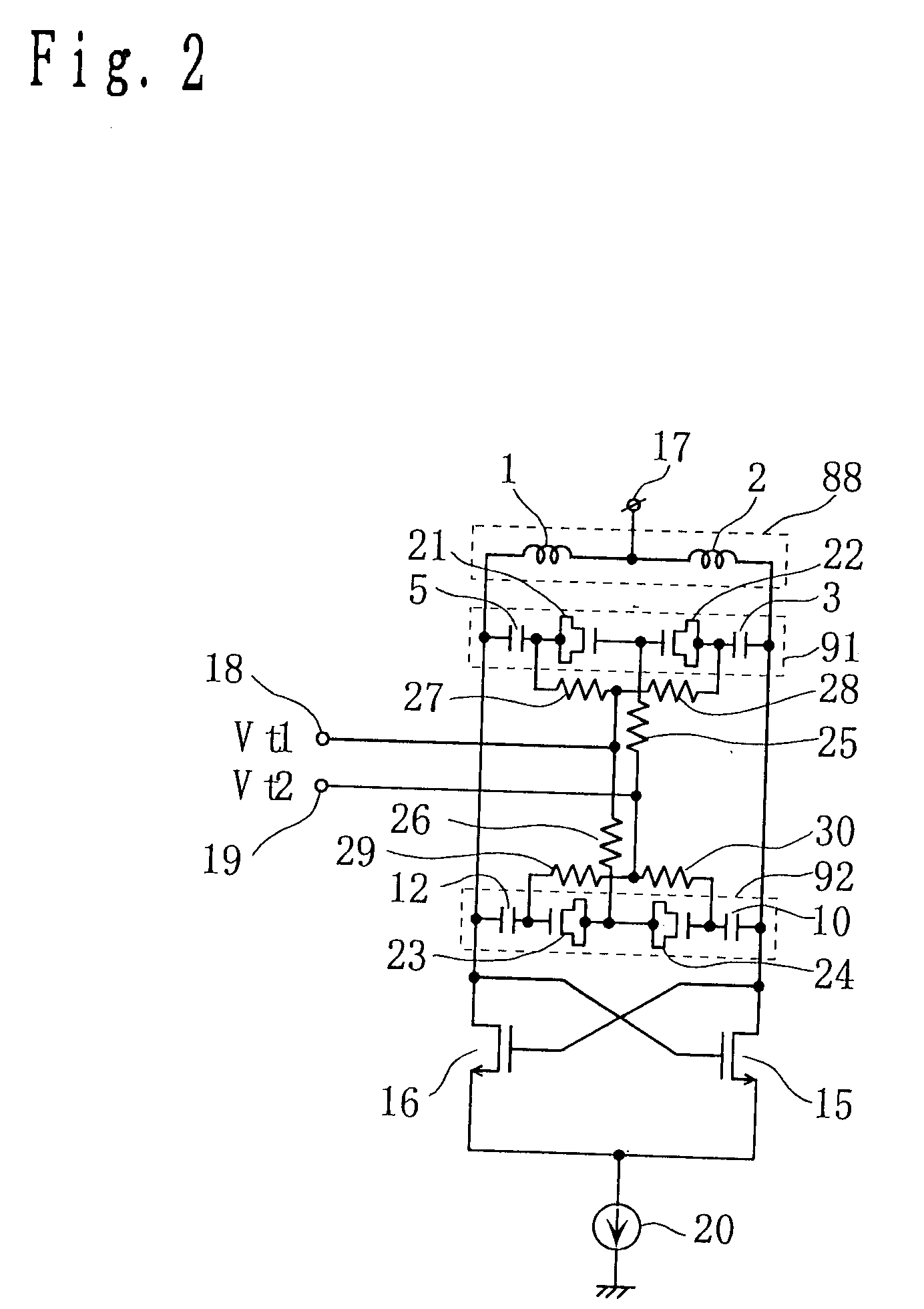
[0104] FIG. 2 shows a circuit representing a configuration of an oscillator according to Embodiment 2 of the present invention.

[0105] In the configuration of the circuit according to the present embodiment, the same components as those of the oscillator according to Embodiment 1 are denoted by the same reference numerals. Their description is omitted. The present embodiment differs from Embodiment 1 in the points described below. A second series connected circuit 91 is composed of the capacitor 5, a varactor 21 as an example of the first variable capacitive impedance element according to the present invention which varactor has a first terminal connected to the capacitor 5, a varactor 22 as an example of the second variable capacitive impedance element according to the present invention which varactor has a second terminal connected to a second terminal of the varactor 21, and the capacitor 3 connected to a first terminal of the varactor 22. A third series conne...

embodiment 3

[0112] (Embodiment 3)

[0113] As Embodiment 3 of the present invention, FIG. 3 shows a PLL circuit that utilizes a voltage-controlled oscillator (VCO) 50 according to Embodiments 1 and 2. The PLL circuit according to Embodiment 3 has a phase frequency comparator (PFD) 51 that compares the phase of a reference signal fr with the phase of an oscillation signal obtained from the voltage-controlled oscillator 50 to output an up signal and a down signal. An up signal output of the phase frequency comparator 51 is in communication with switches 58 and 61 so as to simultaneously open and close them in a controllable manner. A down signal output of the phase frequency comparator 51 is in communication with switches 60 and 59 so as to simultaneously open and close them in a controllable manner.

[0114] Specifically, when the phase frequency comparator 51 outputs an up signal, the switches 58 and 61 are turned on, while the switches 59 and 60 are turned off. On the other hand, when the phase freq...


PUM


Abstract

The present invention provides an oscillator or PLL circuit which can balance the characteristics of a circuit without being affected by noise from a signal line or a supply line. The present invention provides an oscillator comprising a resonance circuit has a first series connected circuit having coils and a power terminal, a second series connected circuit having capacitors and a varactor having directional characteristics, and a third series connected circuit having capacitors and a varactor having directional characteristics. The first, second, and third series connected circuits are connected in parallel. The varactors are connected so as to have opposite directionalities with respect to a connection side of the second and third series connected circuit. The capacities of the varactors are varied by external control. The varied capacities determine an oscillation frequency.

Description

[0001] 1. Field of the Invention[0002] The present invention relates to an oscillator, a PLL circuit, communication equipment, and an oscillating method.[0003] 2. Related Art of the Invention[0004] Voltage-controlled oscillators are widely used as means of generating local oscillation signals for wireless communication equipment (for example, see Japanese Patent Laid-Open No. 2000-224027). FIG. 9 shows an example of a configuration of a conventional voltage-controlled oscillator. In this figure, the voltage-controlled oscillator is composed of coils 101 and 102, capacitors 103 and 106, a variable capacitor (varactor) 105, oscillation transistors 107 and 108, a current source 116, a power terminal 110, and a voltage control terminal 111. In this figure, a bias circuit and the like are omitted.[0005] With reference to FIG. 9, description will be given below of operations of a conventional voltage-controlled oscillator. A parallel resonance circuit is composed of the coils 101 and 102,...

Claims


Application Information

Patent Timeline
IPC IPC(8): H03B1/00H03B5/12H03L7/089H03L7/093H03L7/099H03L7/10
CPCH03B2201/0208H03L7/0896H03L7/093H03L7/099H03B5/1293H03L2207/06H03B5/1228H03B5/1215H03B5/1253H03L7/10H03L7/105
Inventor TAKINAMI, KOJIADACHI, HISASHI
Owner PANASONIC CORP
Why Eureka
Try Eureka