Fixing member, method for producing it, and image forming apparatus comprising the fixing member

a technology of fixing member and fixing member, which is applied in the direction of portable power-driven tools, applications, instruments, etc., can solve the problems of considerable time to heat the heat roller, disadvantages of flexibility, elasticity, and unclear imag

Inactive Publication Date: 2004-04-15
RICOH KK
View PDF1 Cites 23 Cited by
  • Summary
  • Abstract
  • Description
  • Claims
  • Application Information

AI Technical Summary

Problems solved by technology

Moreover, if the unfixed toner layer causes a misalignment and so on at the time of fixing, the image becomes unclear.
However, the heat fixing roller in which the core (i.e. a substrate) is provided with a layer of fluorocarbon resin is advantageous for the releasability, but it is disadvantageous for the flexibility, elasticity, and so on.
However, there were problems such that a considerable time to heat the heat roller till predetermined time is required and also an electric power consumption to heat the whole heat roller is increased.
However this method includes problems as follows;
{circle over (2)} a cost is increased by attaching a system of the replenishment of the silicone oil.
According to the above-mentioned problems, a fixing belt, which does not use the silicone oil, is required.
ure. Therefore, for the conventional fixing roller and the fixing belt, when the releasing layer is formed by burning the fluorocarbon resin with above-mentioned high temperature, depending on a combination with the heat-resistance synthetic rubber composing the inside layer of the elastic layer of the releasing layer, there is a problem of generating a crack on the elastic layer by oxidizing and deteriorating this heat-resistance synthetic ru
When the crack is generated on the elastic layer as this, there were problems that a surface quality of the fixing member is lost, and the toner is remained in a part of the crack generated on the surface of the fixing member, and as a result, defects such as an image fixing fault, and so on are generated by a stained image and an unevenness of a surface.
When loads such as jamming of the transfer paper, a contact of a removed pawl, and so on are imposed, only the releasing layer is peeled so that the melted toner is not able to be released.
As a result, there is a problem that the transfer paper is wound around the fixing roller.
However, there is a limit for thinning a film for the tube of fluorocarbon resin.
Therefore, the fixing roller produced by this method becomes a hard fluorocarbon resin layer of a thick film, and the flexibility of required characteristic is lost, and problems such as generating unevenness of brilliance on the toner surface and unevenness of image on the OHP are caused.

Method used


Image

  • Fixing member, method for producing it, and image forming apparatus comprising the fixing member
  • Fixing member, method for producing it, and image forming apparatus comprising the fixing member
  • Fixing member, method for producing it, and image forming apparatus comprising the fixing member

Examples


embodiment 1

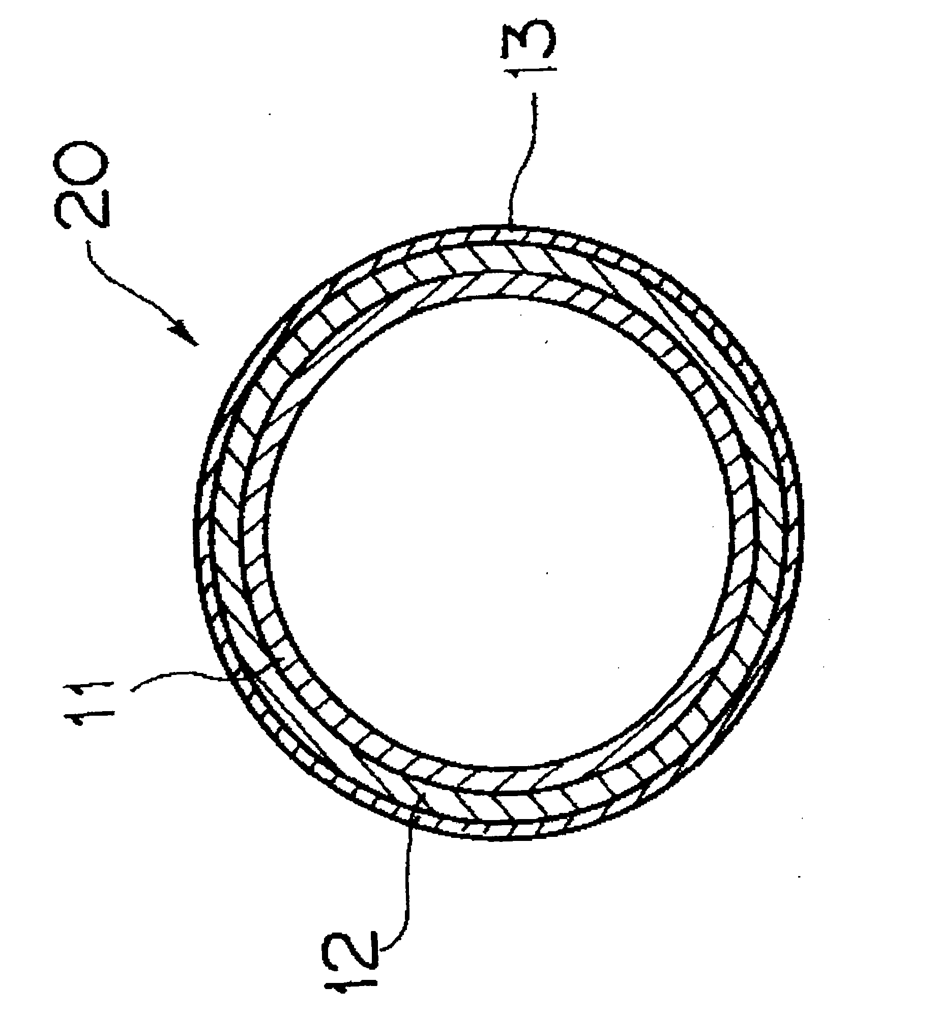
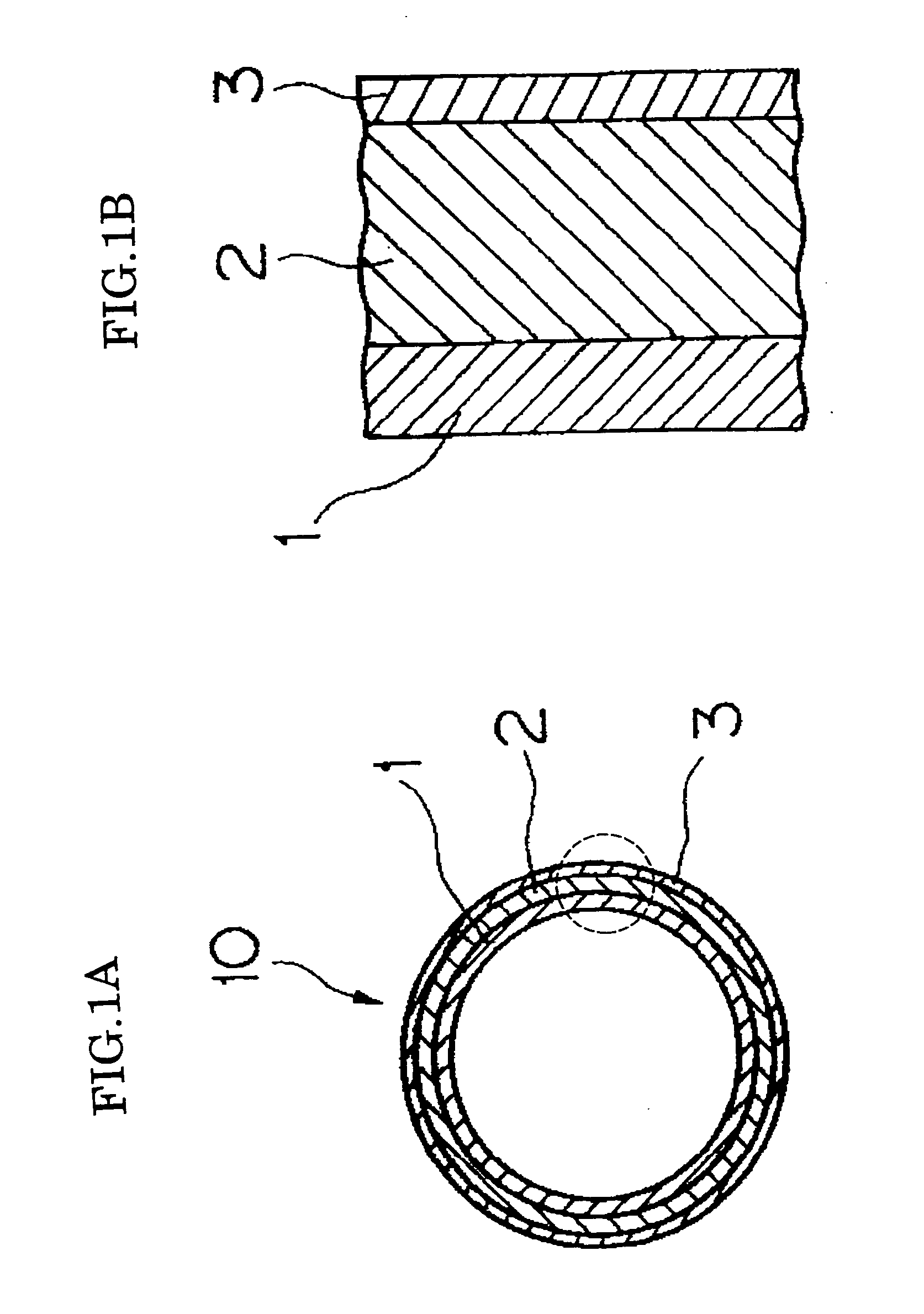
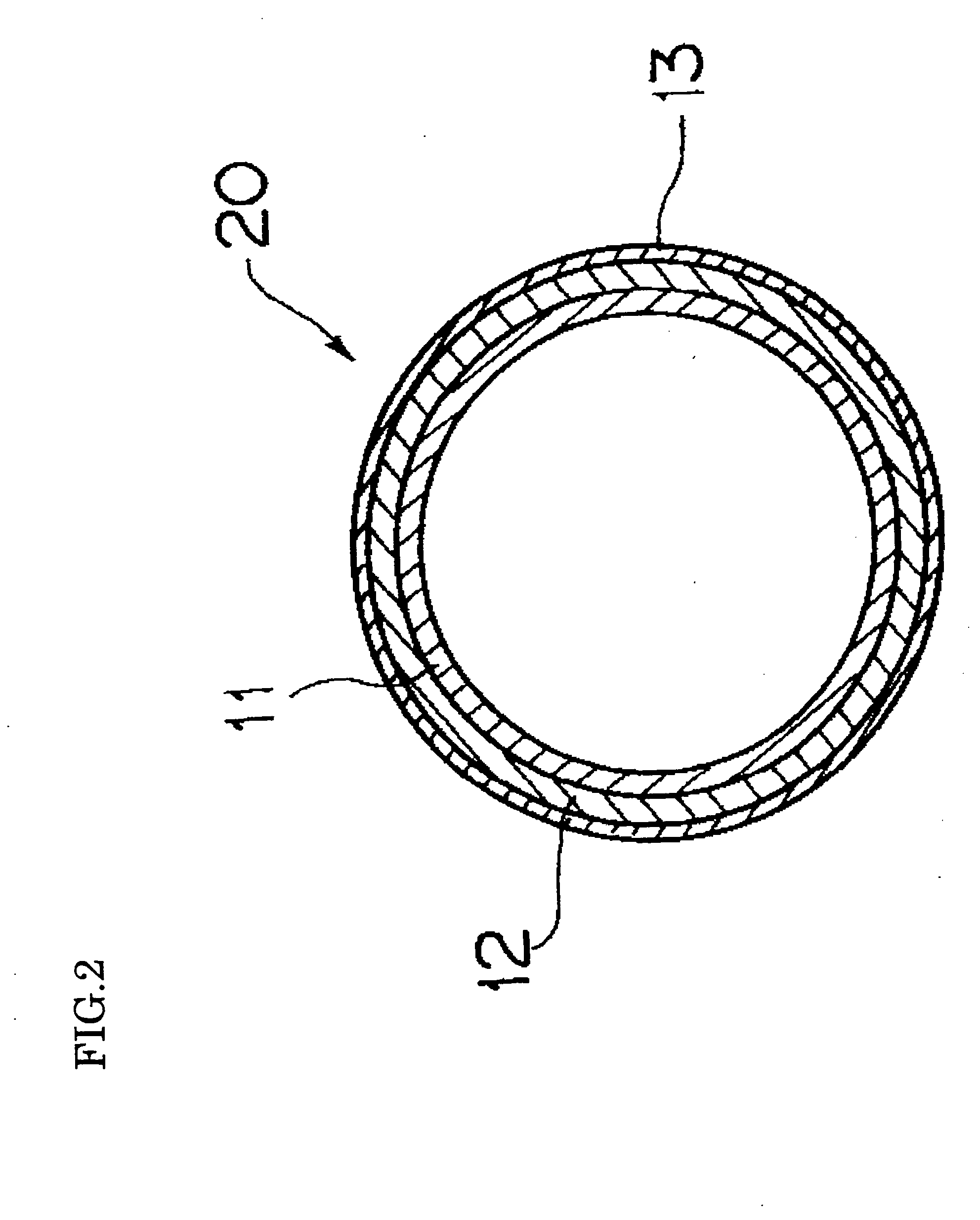
[0078] A fixing roller of the embodiment 1 is formed sequentially by following processes.

[0079] {circle over (1)} a process for forming the first primer layer by applying and drying primer (DY39-0521 TORAY DOW CORNING CO LTD) on a core consisting of aluminum of 40 mm in diameter.

[0080] {circle over (2)} a process for forming the elastic layer by applying and vulcanizing solution of silicone resin (DX35-2083 TORAY DOW CORNING CO LTD) in which the starting temperature for the oxidation containing 5% by weight of iron oxide is 341.degree. C. on the first primer layer.

[0081] {circle over (3)} a process for forming a second primer layer by applying and drying liquid primer for silicone containing fluorocarbon resin (DU-PONT-MITSUI FLUOROCHEMICALS COMPANY, LTD) on this elastic layer.

[0082] {circle over (4)} a process for forming a paint layer by applying and drying dispersion liquid of fluorocarbon resin (PFA345-HP-J DU-PONT-MITSUI FLUOROCHEMICALS COMPANY, LTD) in which a melting point is...

embodiment 2

[0085] For a fixing roller of the second embodiment, in the fourth process of above-mentioned first embodiment, fluorocarbon resin (PFA340HP-J DU-PONT-MITSUI FLUOROCHEMICALS COMPANY, LTD) in which a melting point is 310.degree. C. and a melt flow rate (MFR) prescribed in ASTM D3307 is 10.0 are used. Beside these conditions, the fixing roller of the second embodiment is formed as same as the first embodiment.

embodiment 3

[0086] For a fixing roller of the third embodiment, in the second process of the above-mentioned first embodiment, silicone resin (DX35-20833 Toray Industries, Inc) in which a starting temperature for the oxidation containing 3% by weight of iron oxide is 320.degree. C. is used. In the fourth process of the first embodiment, a paint layer is formed by applying and drying dispersion liquid of fluorocarbon resin (PFA954HP-Plus DU-PONT-MITSUI FLUOROCHEMICALS COMPAY, LTD) in which a melting point is 300.degree. C. and a melt flow rate (MFR) prescribed in ASTM D3307 is 3.0, and then this applying layer is baked for 30 minutes with 320.degree. C. Beside these conditions, the fixing roller of the third embodiment is formed as same as the first embodiment.


PUM

PropertyMeasurementUnit
melting pointaaaaaaaaaa

Abstract

In a fixing member (10) in which an elastic layer made of heat-resistance synthetic rubber and a releasing layer made of fluorocarbon resin are sequentially provided on a substrate, a melting point of the fluorocarbon resin constituting the releasing layer (3) is set to be at least 20° C. lower than a temperature for starting an oxidation of the heat-resistance synthetic rubber constituting the elastic layer (2), and the releasing layer (3) is burned by a temperature which is higher than the melting point of the fluorocarbon resin constituting the releasing layer (3), and a burning temperature which does not exceed the starting temperature for the oxidation of the heat-resistance rubber constituting the elastic layer (2).

Description

[0001] 1. Field of the Invention[0002] The present invention relates to a fixing member such as a roller, a sheet, an endless belt, or the like, which is used for an image forming apparatuses such as an electro-photography copying machine, a laser printer, a facsimile, and so on, and the image forming apparatus, which comprises the fixing member.[0003] 2. Description of the Prior Art[0004] FIG. 3 is an explanatory view showing an image forming apparatus of a conventional electro-photography type. In the image forming apparatus of the conventional electro-photography type 100, for example, a copying machine and a laser printer have a photoconductor drum 101 in which an electrostatic latent image is formed on a surface, an electrification roller 102 in which an electrification treatment is conducted by contacting to the photoconductor drum 101, exposure means 103 such as a laser beam, and so on, a development roller 104 in which a toner is adhered to the electrostatic latent image for...

Claims


Application Information

Patent Timeline
Patent Type & Authority Applications(United States)
IPC IPC(8): F16C13/00G03G15/20
CPCG03G15/2057Y10T428/1359Y10T428/1393Y10S428/906Y10T428/31725Y10T428/3154Y10T428/31663Y10T428/31678Y10T428/31721
Inventor KONDOH, TSUNEAKI
Owner RICOH KK
Why Eureka
Try Eureka