
Well jet device

a jet pump and well technology, applied in the direction of jet pumps, non-positive displacement pumps, borehole/well accessories, etc., can solve the problems of reducing the strength of the unit, lowering the capacity of the jet pump, and the diameter of the passage for supplying the pumped out medium cannot be taken arbitrarily, so as to improve the reliability of the well jet unit.

Inactive Publication Date: 2004-04-15
KHOMYNETS ZINOVIY DMITRIEVICH
View PDF11 Cites 44 Cited by
  • Summary
  • Abstract
  • Description
  • Claims
  • Application Information

AI Technical Summary

Benefits of technology

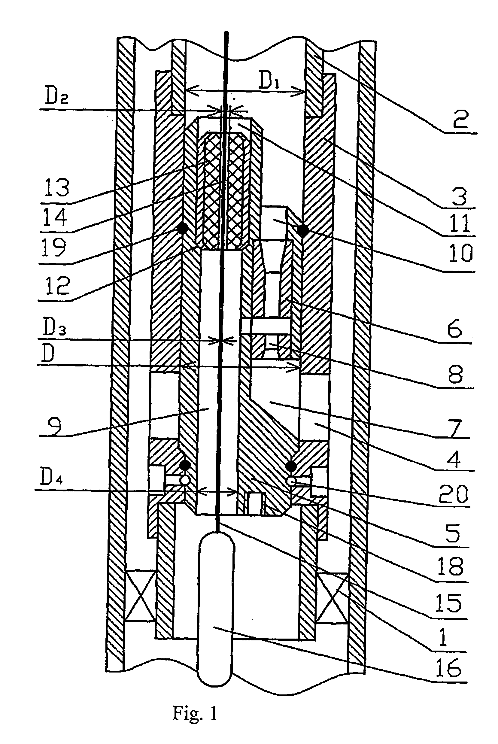
"The invention aims to improve the operation and reliability of a well jet unit by optimizing the arrangement and dimensions of its components. This includes the packer, piping string, and jet pump housing. The diameter of the passage for supplying the pumped out medium is at least 2 mm higher than the diameter of the cable, and sealing rings and a retaining mechanism are installed on the housing of the jet pump. The invention also includes a threaded hole in the bottom part of the jet pump for attaching autonomous measuring equipment. The objective of the invention is to increase the reliability of the well jet unit and expand the range of studies conducted in the well."

Problems solved by technology

It has been found out, in particular, that the diameter of the passage for supplying the pumped out medium may not be taken arbitrarily.
It is due to the fact that a too large diameter of the passages results in a reduction in the strength of the unit, but a too small diameter of those passages results in lowering the capacity of the jet pump.

Method used


Image

  • Well jet device
  • Well jet device
  • Well jet device

Examples


Embodiment Construction

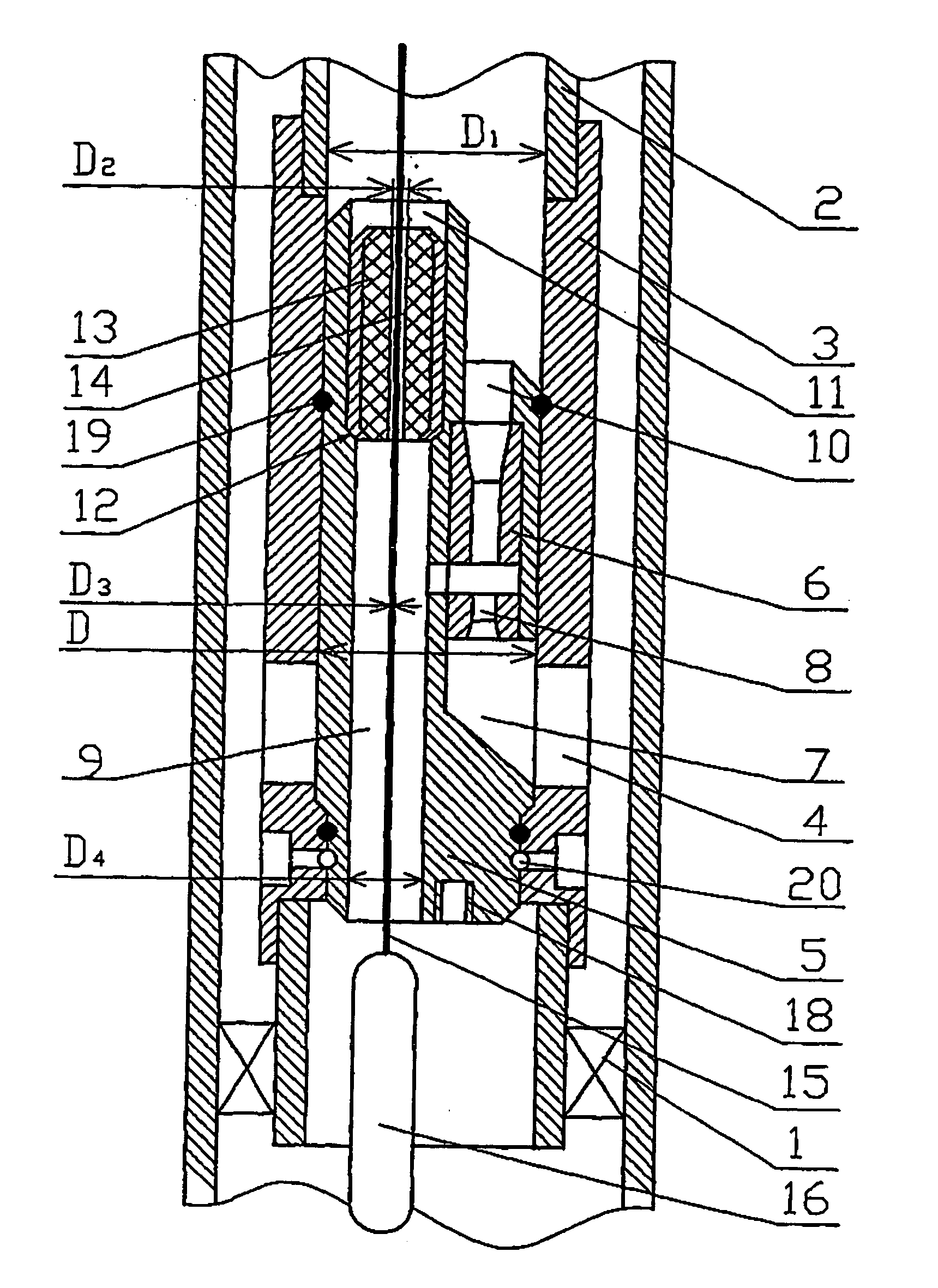
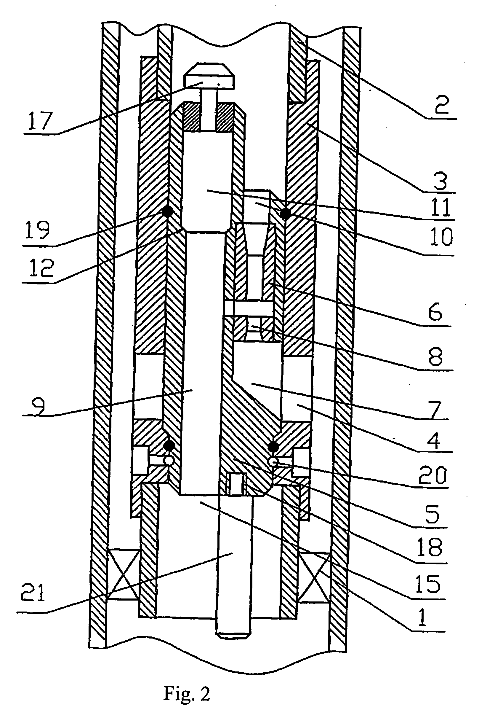
[0012] The proposed well jet unit comprises a packer 1, a piping string 2, having a support 3 wherein drain ports 4 are made and onto which a jet pump 6 with its housing 5 is installed, the said housing 5 comprises: a passage 7 in communication with drain ports 4 for supplying an active medium to the nozzle 8 of the jet pump 6 from the space surrounding the piping string 2, a passage 9 for supplying the medium pumped out of the well to the jet pump 6 and a passage 10 for removing a medium mixture from the jet pump 6 into the inner cavity of the piping string 2 above the jet pump 6, and in the housing 5 above the passage 9 for supplying the pumped out medium a through passage 11, being in communication with the passage 9 and being made with a mounting face 12 for installing a sealing assembly 13, and the sealing assembly 13 comprises a through passage 14 with the possibility of leading, through it and the passage 9 for supplying the pumped out medium, a cable 15 for the purpose of in...


PUM


Abstract

The invention relates to pumping equipment. The inventive jet device comprises a packer, a pipe column and a cradle in which drain ports are embodied and on which a jet pump is mounted in a body. Said body is provided with a channel for supplying an active medium to the nozzle, a channel for supplying a pumped-out medium, and a channel for evacuating the mixture of said mediums. The body also comprises a through channel embodied therein above the channel for supplying a pumped-out medium, connected thereto and used for arranging a sealing unit. Said sealing unit comprises a channel for passing the pumped out medium of a cable and a channel for supplying the pumped out medium of the cable used for arranging instruments and equipment. The channel for supplying a pumped-out the active medium is connected to the drain ports and to the space around the pipe column by means of said ports. The channel for evacuating the mixture the mediums from the jet pump is connected to the internal space of tubes above the jet pump. The sealing unit is embodied in such a way that it makes it possible to arrange thereinside a mechanism for bringing in the well and extracting therefrom the body containing the jet pump. A threaded hole for connecting autonomous measuring instruments to the body is embodied in the lower part thereof.

Description

[0001] This invention relates to the field of pumping engineering, mainly to downhole jet units for oil production.PRIOR ART[0002] Known in the art is a downhole jet unit comprising a jet pump installed on the production string in the well and a geophysical instrument placed in the production string below the said jet pump (RU 2059891 C1).[0003] The said jet pumping unit enables to pump different extracted media, e.g., oil, out of the well with the simultaneous treatment of the extracted medium and the well formation zone, but the said unit provides for supply of a working medium to the nozzle of the jet unit along the string, which in some cases narrows the field of application of the said unit.[0004] The closest, as to its technical essence and the achievable result, to this invention is a downhole jet unit comprising a packer, a piping string having a support wherein drain ports are made and onto which a jet pump with its housing is installed, the said housing of the said pump co...

Claims


Application Information

Patent Timeline
Patent Type & Authority Applications(United States)
IPC IPC(8): E21B33/08F04F5/54E21B43/12F04F5/24F04F5/46
CPCE21B33/08F04F5/464F04F5/24E21B43/124
Inventor KHOMYNETS, ZINOVIY DMITRIEVICH
Owner KHOMYNETS ZINOVIY DMITRIEVICH
Learn More