Exhaust gas purifying filter with reinforced peripheral area and method for manufacturing the same

Inactive Publication Date: 2004-04-15
DENSO CORP
View PDF4 Cites 52 Cited by
  • Summary
  • Abstract
  • Description
  • Claims
  • Application Information

AI Technical Summary

Problems solved by technology

However, if the partition wall is made thinner and the porosity is increased, the mechanical strength of the ceramic honeycomb structure is reduced.
Therefore, a problem arises that the end portions of the ceramic honeycomb structure become more likely to fracture when catalysts are provided, when the structure is attached to an internal combustion engine, or the like.
However, no definition is given as to the range of the peripheral area to be filled with the plug material in the conventional ceramic honeycomb structure.
If the range of the peripheral area to be filled with the plug material is too large, a problem arises that the exhaust gas filtration area decreases and, at the same time, the pressure loss increases.
On the other hand, if the peripheral area to be filled with the plug material is too smal

Method used


Image

  • Exhaust gas purifying filter with reinforced peripheral area and method for manufacturing the same
  • Exhaust gas purifying filter with reinforced peripheral area and method for manufacturing the same
  • Exhaust gas purifying filter with reinforced peripheral area and method for manufacturing the same

Examples


first embodiment

[0086] The exhaust gas purifying filter and the method for manufacturing the same according to the present invention are described below by using FIG. 1 to FIG. 11.

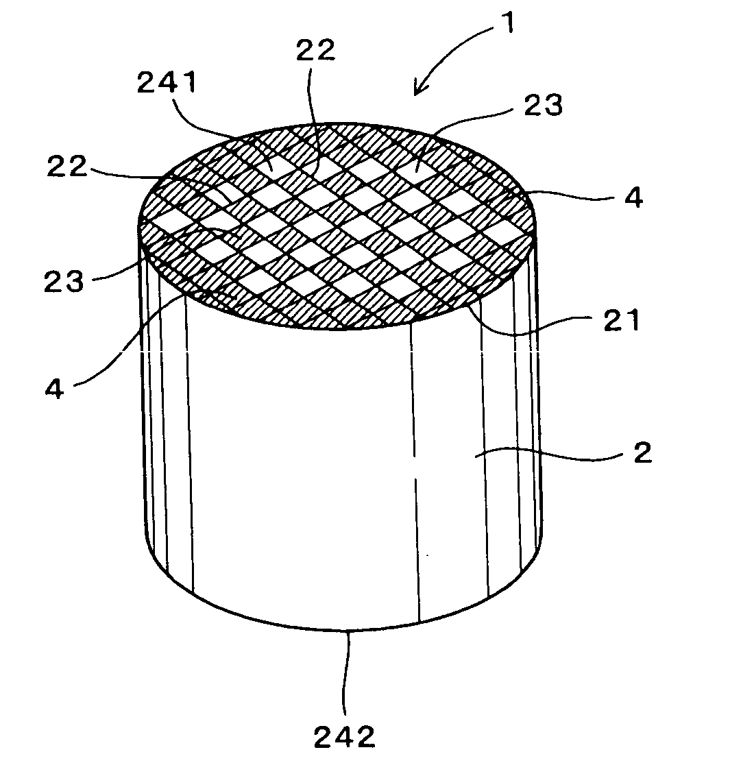
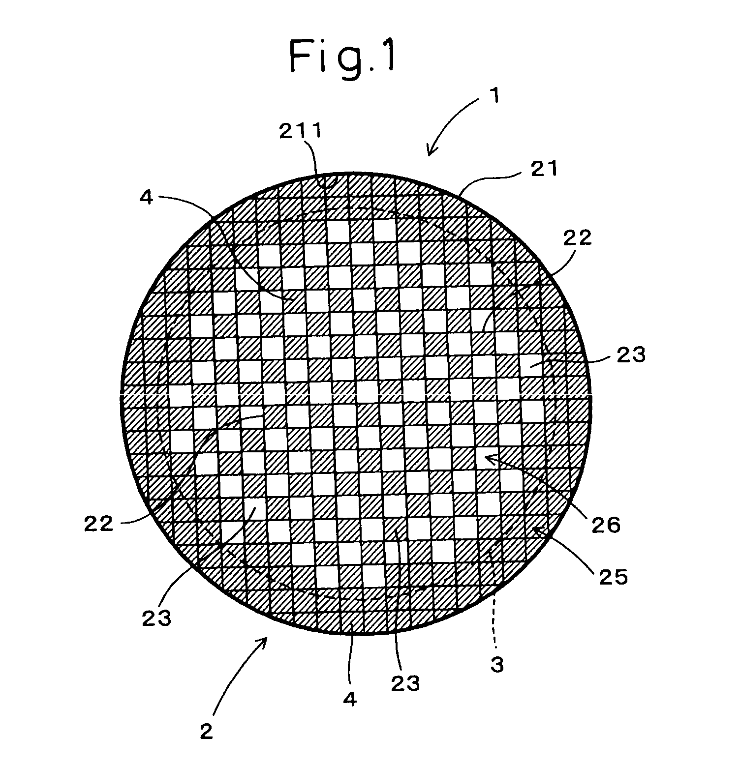
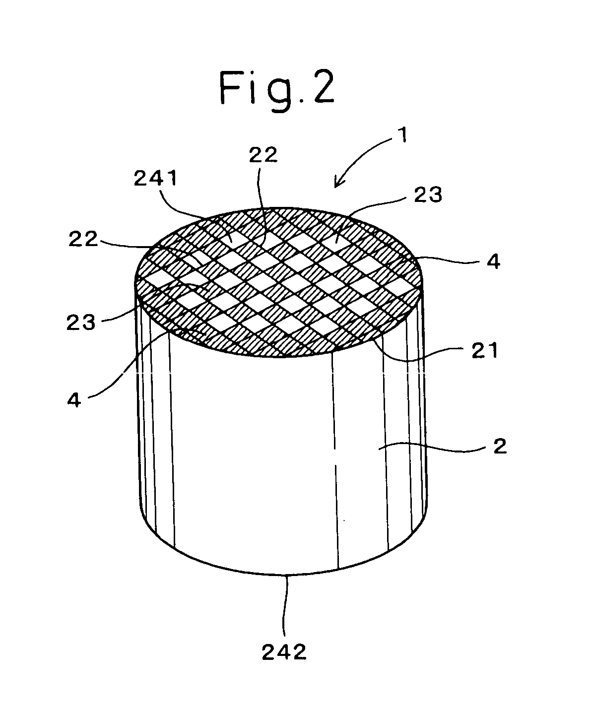
[0087] As shown in FIG. 1 to FIG. 3, an exhaust gas purifying filter 1 has a ceramic honeycomb structure 2 comprising a surrounding wall 21, partition walls 22 arranged in a honeycomb pattern within the surrounding wall 21, and a plurality of cells 23 partitioned by the partition walls 22 and, at the same time, penetrating through both end faces 241 and 242.

[0088] On both end faces 241 and 242 of the ceramic honeycomb structure 2, if a virtual line 3 is drawn by continuously connecting points at a distance of 1.0 to 3.0 times the cell pitch in the direction toward the center from an inner surface 211 of the surrounding wall 21, not less than 90% of a peripheral area 25 outside the virtual line 3 are blocked with plug material 4, as shown in FIG. 1.

[0089] The definition of the cell pitch is defined by the above-mentioned e...

second embodiment

[0115] In the present embodiment, the exhaust gas purifying filter 1 is manufactured by a method different from that in the first embodiment, as shown in FIG. 12 and FIG. 13.

[0116] In other words, on the end face 241 (242) of the ceramic honeycomb structure 2 shown in the first embodiment, the mask tape 5 is pasted to the central area 26 within the virtual line 3, as shown in FIG. 12.

[0117] Therefore, the mask tape 5 has a shape whose outline coincides with the virtual line 3.

[0118] Then, before the plugging process, as shown in FIG. 13, the drilling process is carried out for drilling the mask tape 5 which covers the openings 231 of the cells 23 through which the virtual line 3 passes. In this drilling process, the mask tape 5 in the central area 26 within the virtual line 3 is also drilled in a checkerboard pattern. In FIG. 13, reference number 55 denotes the drilled parts.

[0119] Others are the same as the first embodiment.

[0120] According to the present manufacturing method, it i...

third embodiment

[0122] In the present embodiment, the plug material 4 is partly formed in the cells 3 through which the virtual line 3 passes in the exhaust gas purifying filter 1, as shown in FIG. 14.

[0123] In other words, the forming process and the masking process are first carried out as in the second embodiment (refer to FIG. 12). Then, the cells 23 through which the virtual line 3 passes are not drilled in the drilling process.

[0124] Others are the same as the second embodiment.

[0125] Due to this, the plug material 4 is formed as a partial plug in the cells 3 through which the virtual line 3 passes, as shown in FIG. 14. In this case, it is possible to reduce the number of man-hours for the drilling process by further reducing the number of positions to be drilled.

[0126] Others have the same operation / working-effect as that in the second embodiment.


PUM

PropertyMeasurementUnit
Fractionaaaaaaaaaa
Thicknessaaaaaaaaaa
Thicknessaaaaaaaaaa

Abstract

An exhaust gas purifying filter having a high strength and an excellent efficiency of exhaust gas purification and a method for manufacturing the same are provided. An exhaust gas purifying filter 1 comprises a ceramic honeycomb structure 2 having a surrounding wall 21, partition walls 22 provided in a honeycomb pattern within the surrounding wall 21, and a plurality of cells 23 partitioned by the partition walls 22 and penetrating through end faces 241, 242. If a virtual line 3 is drawn on the end faces 241, 242 of the structure 2 by continuously connecting points at a distance of 1.0 to 3.0 times the cell pitch in the direction toward the center from an inner surface 211 of the surrounding wall 21, not less than 90% of a peripheral area 25 outside the virtual line 3 is blocked with plug material 4.

Description

[0001] 1. Field of the Invention[0002] The present invention relates to an exhaust gas purifying filter for purifying an exhaust gas, by collecting particulates from the exhaust gas of an internal combustion engine, and a method for manufacturing the same.[0003] 2. Description of the Related Art[0004] Conventionally, an exhaust gas purifying filter having a ceramic honeycomb structure acts as an exhaust gas purifying filter, for purifying an exhaust gas, by collecting particulates from the exhaust gas of an internal combustion engine.[0005] The ceramic honeycomb structure comprises a surrounding wall, partition walls provided in a honeycomb pattern within the surrounding wall, and a plurality of cells partitioned by the partition walls and, at the same time, penetrating through from one end face of the ceramic honeycomb structure to the other.[0006] In order to improve the efficiency of purification of the exhaust gas purifying filter, it is desired to make the partition walls thinn...

Claims


Application Information

Patent Timeline
IPC IPC(8): F01N3/02B01D39/00B01D39/20B01D46/00B01D46/24B01D53/94B01J32/00B01J35/04B28B11/00C04B38/00F01N3/022
CPCB01D46/2429Y10T428/24744B01D46/2455B01D46/2459B01D46/2466B01D46/2474B01D2046/2433B28B11/006B28B11/007C04B38/0006C04B2111/00793F01N3/0222F01N2330/06B01D46/2451Y10T428/24777Y10T428/24157Y02T10/20Y10T428/131Y10T428/24149Y10T428/24793C04B35/195C04B38/0009Y02T10/12B01D46/24491B01D46/2482
Inventor ISHIHARA, MIKIONISHIMURA, MAMORU
Owner DENSO CORP
Why Eureka
Try Eureka