Structure of floor slab bridge

a technology of floor slabs and bridges, applied in bridge construction, bridge materials, construction, etc., can solve the problems of affecting the appearance of the floor

Inactive Publication Date: 2004-04-22
ASAHI ENG CO LTD +1
View PDF10 Cites 9 Cited by
  • Summary
  • Abstract
  • Description
  • Claims
  • Application Information

AI Technical Summary

Problems solved by technology

In addition, since the fastening parts are exposed from the side plates 16, i.e., from the concrete layer, the fastening parts are rotten by wind, rain or the like to degrade their original function and to spoil the outer appearance of the floor slab bridge.
Moreover, such a very troublesome work is required as to fillet weld each and every T-shaped steel or H-shaped steel over its entire length to the bottom plate 3 and the steel sheet piles 11 at constant intervals.
Thus, the working term is increased and the cost is increased, too.

Method used


Image

  • Structure of floor slab bridge
  • Structure of floor slab bridge
  • Structure of floor slab bridge

Examples


Embodiment Construction

[0035] Embodiments of the present invention will now be described hereinafter with reference to FIGS. 1 through 9.

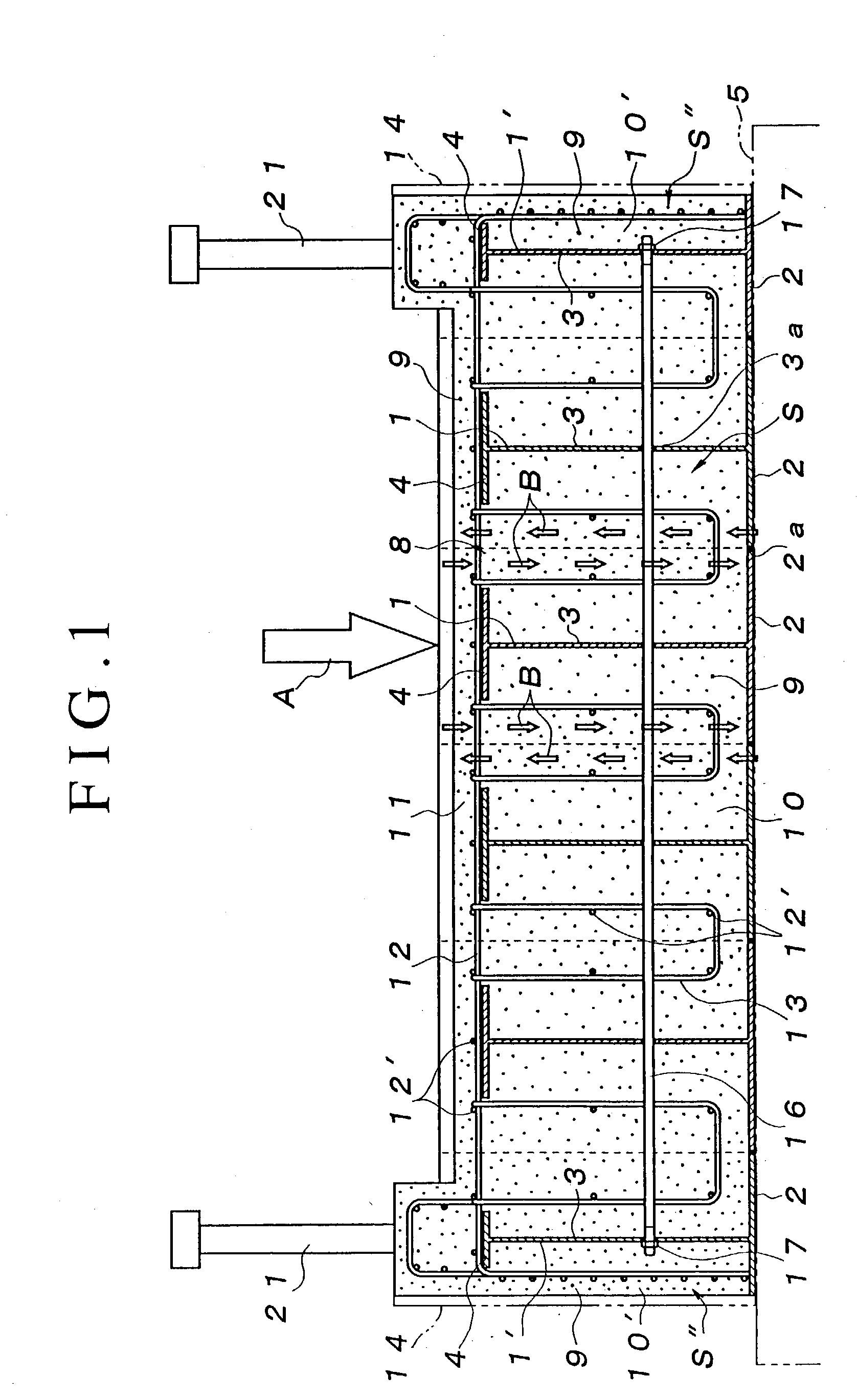
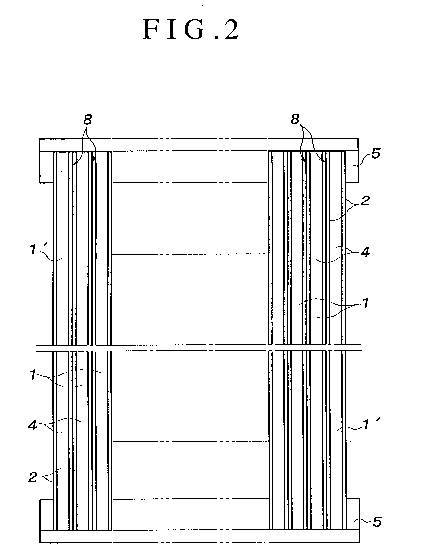
[0036] As shown in FIGS. 1, 2, 6 and 8, a plurality of columnar H-shaped steels 1 each having an lower flange 2 and an upper flange 4 joined together through a web plate 3, that is, a plurality of commercially available H-shaped steels of JIS specifications, are used. As shown in FIGS. 2, 3 and 9, those columnar H-shaped steels 1 are arranged in side-by-side relation between adjacent bridge legs 5 such that end faces 2a of the adjacent lower flanges 2 are abutted with each other.

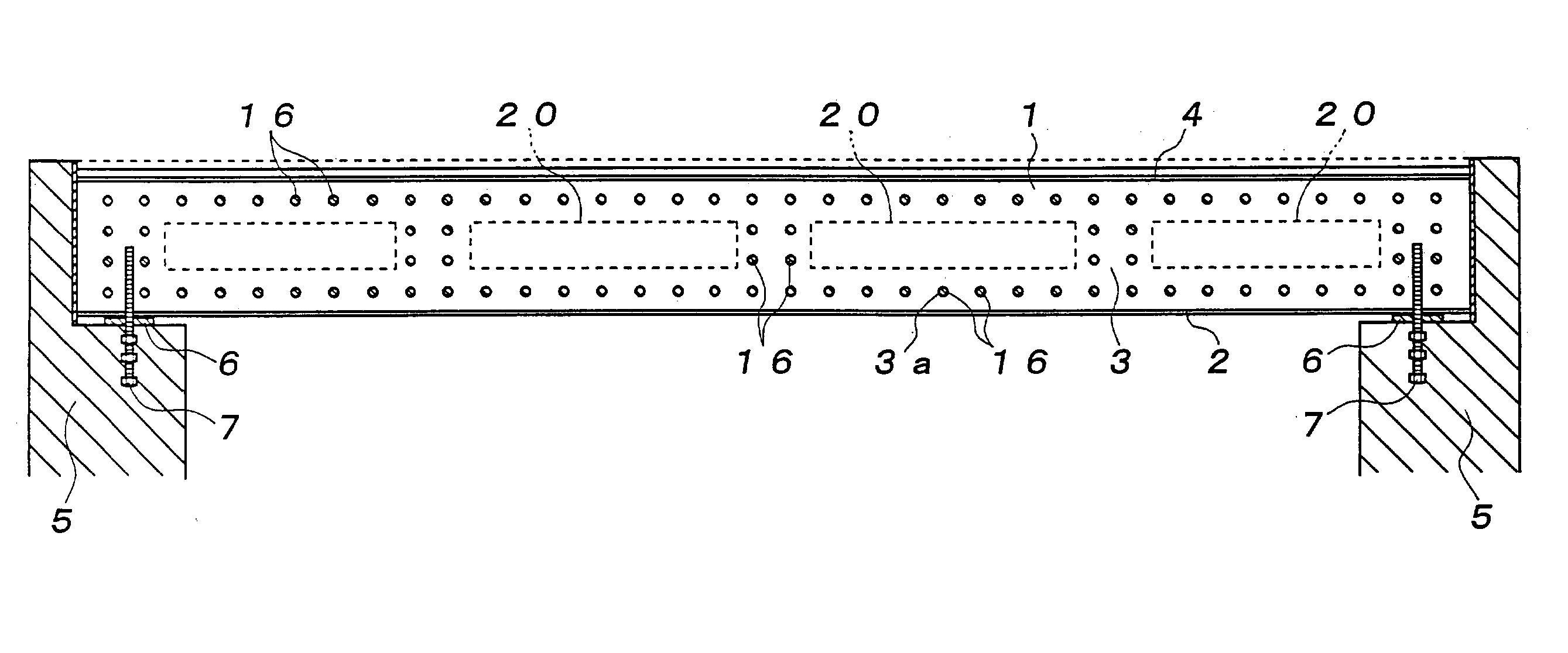
[0037] As shown in FIGS. 3 and 9, the opposite ends of the columnar H-shaped steel 1 are supported on seat surfaces of the adjacent bridge legs 5, 5 through rubber bearings 6 or the like, and the opposite ends of the lower flange 2 are attached to the bridge legs 5 through anchor bolts 7.

[0038] As shown in FIG. 4, each upper flange 4 is dimensioned smaller in width than each lower flange 2, so th...


PUM


Abstract

To properly construct a floor slab bridge by forming a main girder structure of the floor slab bridge in a bridge using commercially available columnar H-shaped steels and then applying concrete thereto. A construction of the floor slab bridge comprises a plurality of columnar H-shaped steels 1 each disposed between adjacent bridge legs 5, 5 and arranged in side-by-side relation with an end face 2a of a lower flange 2 abutted with a corresponding end face 2a of the adjacent columnar H-shaped steel 1, a lower concrete layer 10 formed by placing concrete in space S defined between the upper and lower flanges 4 and 2 and between the adjacent web plates 3 through a concrete inlet port 8 formed between the adjacent upper flanges 2, an upper concrete layer 11 formed by placing concrete 9 on the upper flange 4, an iron reinforcement 12 is horizontally disposed on the upper flanges 4, an iron reinforcement 13 being suspended in the space S from the horizontal iron reinforcement 12 through the concrete inlet port 8, and the horizontal iron reinforcement 12 being embedded in the upper concrete layer 11 and the suspending iron reinforcement 13 being embedded in the lower concrete layer 10.

Description

[0001] 1. Field of the Invention[0002] This invention relates to a structure of a floor slab bridge in a bridge built up in river or on land, and more particularly to a structure of a floor slab bridge in which a columnar H-shaped steel is used as a main girder material.[0003] 2. Related Art[0004] A floor slab bridge is disclosed by Japanese Patent Application Laid-Open Publication No. H09-221717 as typically illustrated in its FIGS. 1 and 2, in which steel sheet piles 11 are used as a bottom plate, T-shaped steels or H-shaped steels (main girder member 13) are welded to the steel sheet piles 11 such that the T-shaped steels or H-shaped steels are spacedly arranged thereon, each and every adjacent steel sheet piles 11 are joined together by pawls 12 disposed at left and right side end faces of each steel sheet pile 11, concrete is placed in space between an upper flange of each T-shaped steel or H-shaped steel and the steel sheet pile 11 through a concrete inlet port which is formed...

Claims


Application Information

Patent Timeline
Patent Type & Authority Applications(United States)
IPC IPC(8): E01D1/00E01D2/00E01D19/12E01D101/30
CPCE01D2/00E01D2101/268E01D19/125
Inventor TOKUNO, MITSUHIROTSUDA, KAZUTOSHISAITO, FUMIHIRO
Owner ASAHI ENG CO LTD
Why Eureka
Try Eureka